


The design of a composite floor begins with a series of initial considerations that will determine the most suitable structural solution for each project. Before dimensioning, the variables that influence the composite behavior of the steel deck and the reinforced concrete slab must be defined in order to ensure an efficient and balanced floor section.
Project Span Range
The span range is one of the main factors in composite floor design. The distances between supports, measured center-to-center of the structure, are typically between 2 and 5 meters. From a structural efficiency standpoint, it is advisable to maintain uniform spans of approximately 2 to 3 meters in order to optimize slab depth and steel consumption.
The practical tested application limit is around 5.00 meters. Beyond this distance, the system may be verified through specific structural calculation, but it falls outside the tested range and progressively loses structural efficiency.
Permanent and Live Loads
Load definition is another essential aspect of the design phase. The range of allowable loads depends on the intended use, the span between supports, the total slab depth, and the configuration of the selected profile.
For guidance:
With reduced spans and slab depths (for example, 120 mm slabs and spans close to 2 m), high overload capacities can be achieved relative to the span.
With intermediate spans and slab depths (for example, 150 mm slabs and spans close to 3.5 m), allowable overloads progressively decrease.
With larger spans and slab depths (for example, 200 mm slabs and spans close to 5 m), allowable values are lower due to increased stresses and deflections.
These values should be considered only as preliminary reference data. Final verification requires structural calculation in accordance with load combinations and limit states established by current regulations.
Uniform Support Distribution
The structural behavior of a composite floor largely depends on the regularity of spans. Whenever possible, a uniform arrangement of supports allows the slab to be designed with more efficient depth and balanced load distribution.
Conversely, an irregular arrangement may influence the design by generating stress concentrations that require increasing slab depth or modifying the structural configuration.
Influence of Propping on Design
Depending on site conditions, solutions with or without propping may be adopted during the construction phase. The choice between a simply supported span (single span) or a continuous multi-span arrangement directly affects the need for temporary props.
When avoiding propping is required, special attention should be given to:
the selection of the composite deck profile and its thickness;
the distance between supports;
the structural layout design;
the total slab depth.
In certain configurations and with standard slab depths, spans of approximately 4 to 5 meters can be achieved without intermediate propping, depending on the profile model and design conditions. In all cases, the adopted solution must be specifically verified for each project.
Minimum Slab Depth According to Fire Requirements
Fire resistance is a determining factor in the dimensioning of a composite floor. When the project requires classifications higher than REI 30, the total slab depth becomes a key variable in meeting regulatory compliance.
Regulations establish minimum slab depths depending on the selected profile and required performance level. Additionally, a leveling layer or floor finish with equivalent thermal characteristics may be considered within the limits established by applicable regulations.
Selection of the Composite Deck Profile
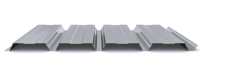
Based on the previous design conditions, the Incoperfil range of composite profiles allows the structural solution to be adapted to each project:
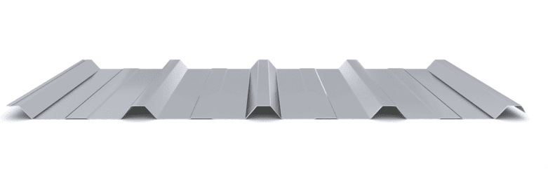
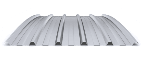
INCO 70.4 Composite: medium-rib profile suitable for shallow slabs and moderate loads.
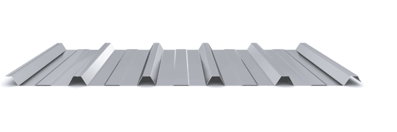
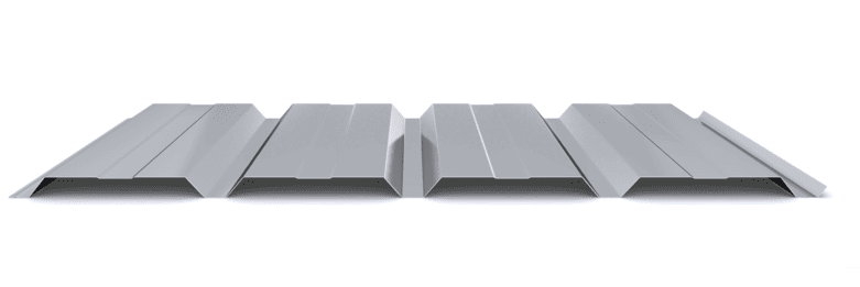
INCO 100.3 Composite: versatile profile for medium spans in unpropped configurations, subject to structural verification
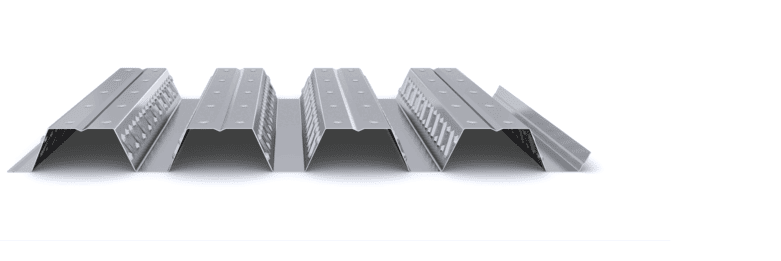
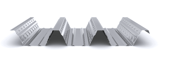
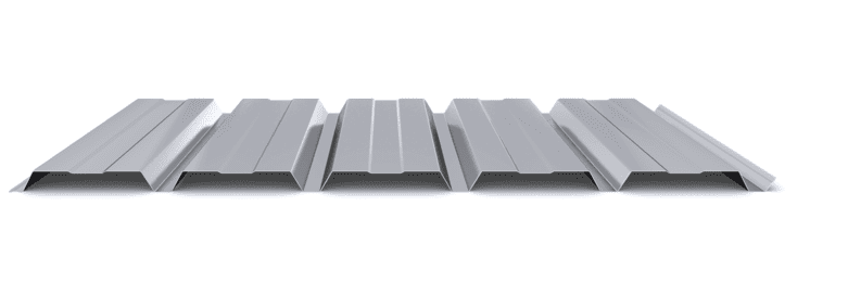
INCO 100.3 R Composite: variant intended for higher fire-resistance requirements.
All models are manufactured in galvanized steel or with corrosion-protection coatings, in compliance with CE marking according to UNE-EN 1090.
Conclusion
Designing a composite floor requires a comprehensive analysis of spans, loads, support distribution, construction conditions, and fire-resistance requirements. Proper definition of these variables makes it possible to select the appropriate profile and slab depth, ensuring an efficient, safe, and code-compliant structural solution.
Incoperfil Technical Manual
For a complete definition of the system, design criteria, calculation bases, resistance tables, construction details, and installation procedures, consult the Incoperfil Composite Slab Technical Manual, available upon registration in the Documentation section of the website.
Last update: February 2026
© Incoperfil. All rights reserved.
The technical content of this article forms part of the Composite Flooring Technical Manual and the documentation registered by Incoperfil with ColorURIS (Act No. 1-INCOPERFIL-12.2025).