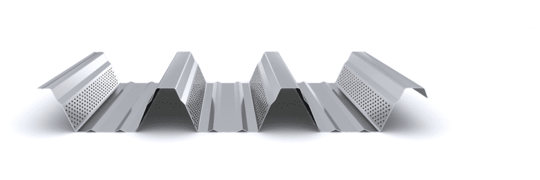
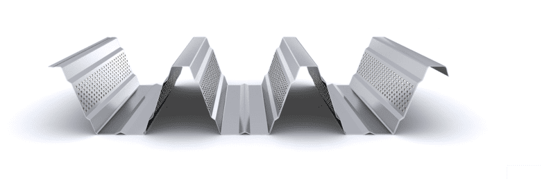
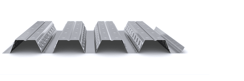
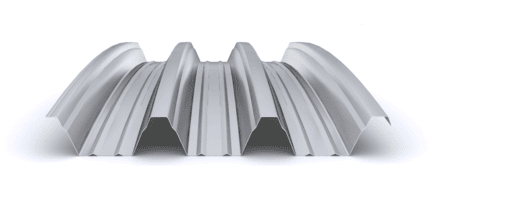
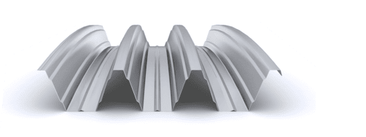
Request a
calculation form

Home / Perforated

Perforated

The perforated finish consists of perforating the material before being shaped, mainly in interior applications to improve acoustic absorption or outdoors to act as solar control.

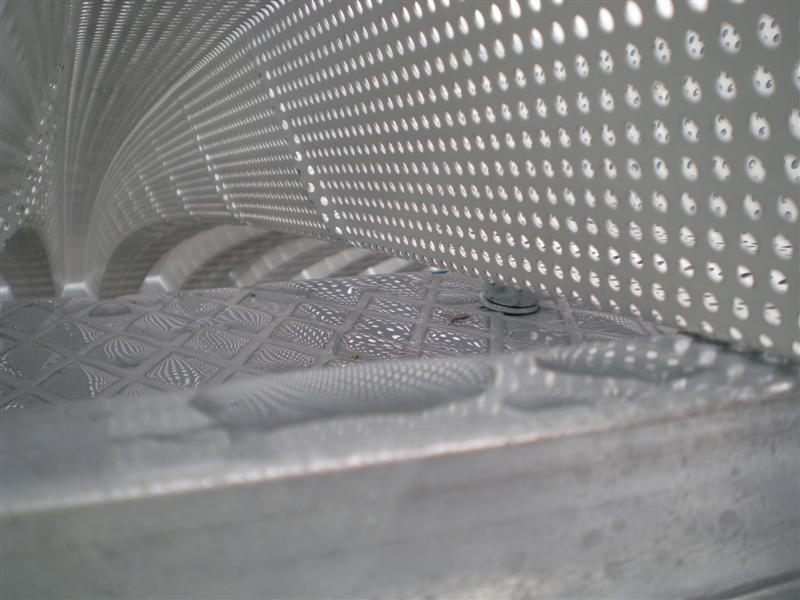
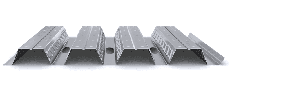
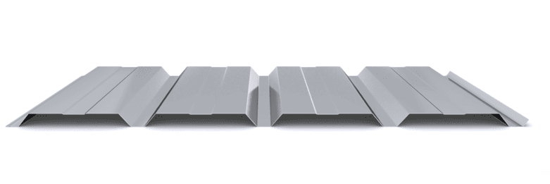
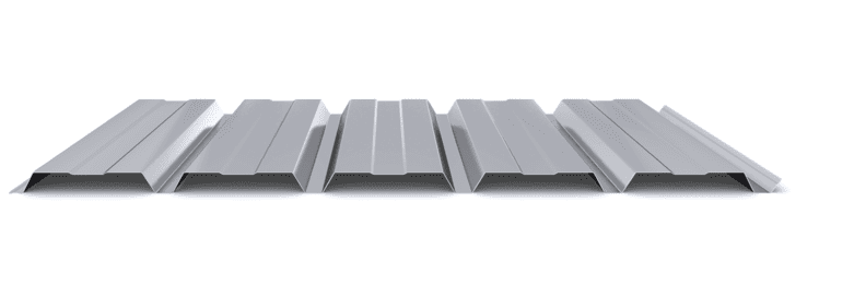
The most common types of perforation are made using circular perforations distributed in staggered fashion, with diameters of 3 and 5 mm. The R3T6 perforation type, where R is the diameter and T is the separation between centers of circumference in mm, is generally used for perforations that cover the entire surface of the material. On the other hand, type R5T8 is used for drilling only in the webs of deep height profiles. Other standardized drilling patterns can be used upon request.

The material drilling process is carried out after the zinc coating and painting processes. As a result, at the edges of each perforation, the steel substrate is exposed, stripped of zinc and paint. For this reason, the use of microperforated steel materials is limited to indoor environments with a very low or low corrosivity category, type C1 or C2. The use of materials such as zinc-magnesium (ZM), which ensures protection of exposed edges in aggressive environments, or a subsequent process of lacquering the parts, constitute the only options to guarantee adequate corrosion resistance of the perforated materials. , both indoors and outdoors.

Therefore, the use of a perforated material is due to technical, energy or aesthetic needs, such as:

  • Improved acoustic absorption indoors.
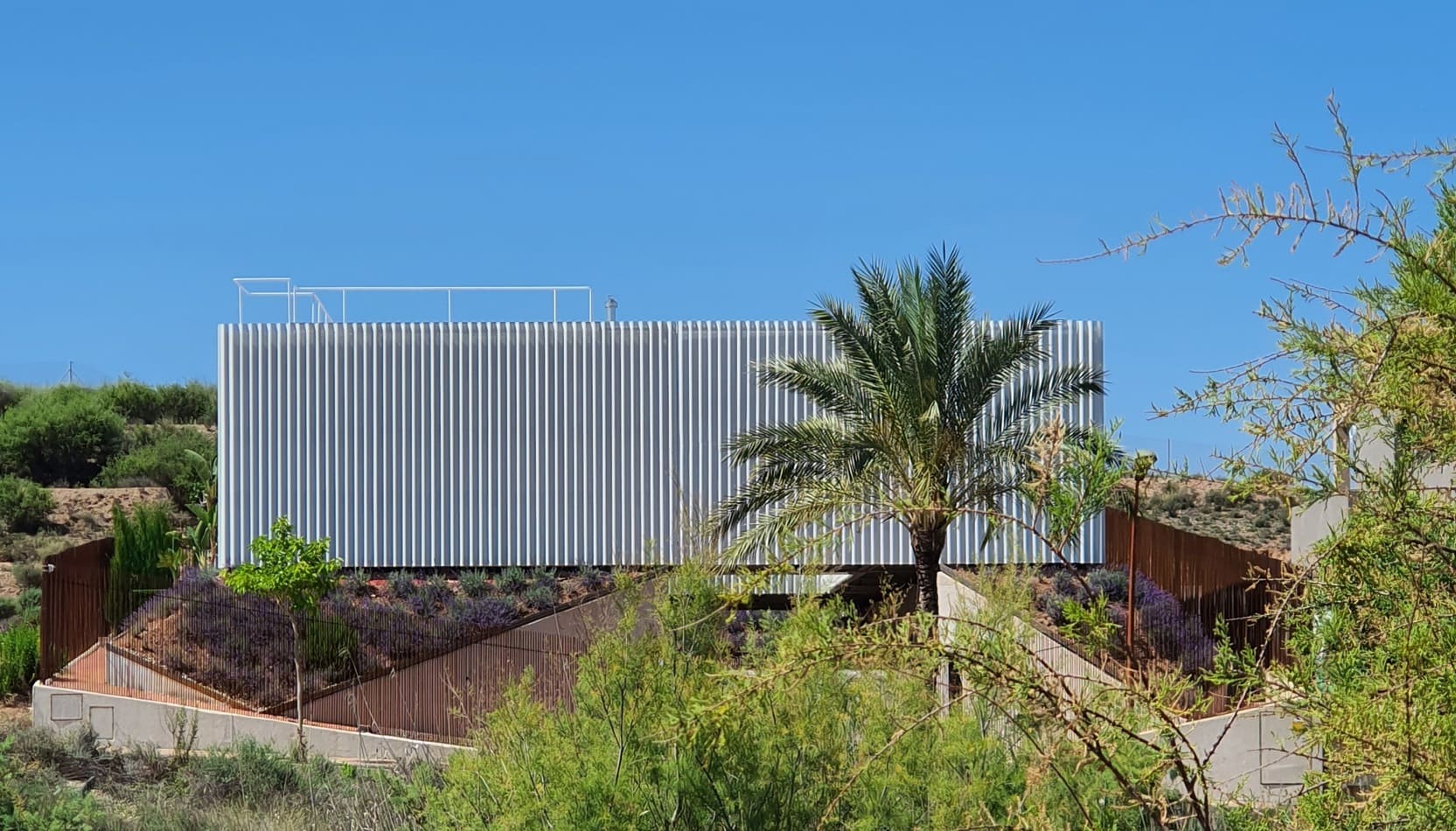
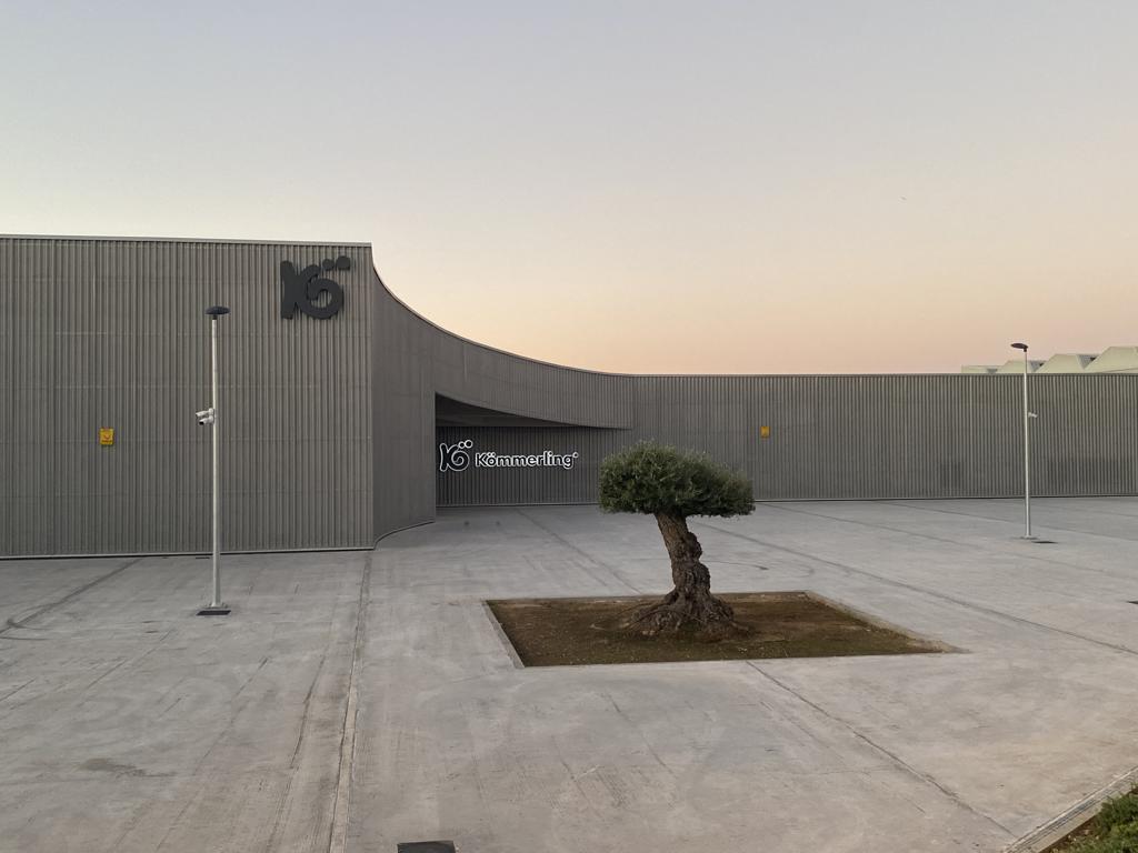
  • Regulation of solar incidence inside the building.
  • Unification of the façade design, covering the gaps and blind parts under the same envelope.

Start designing yout project

Request calculation report

Complete the form below to receive a detailed report justifying the most suitable enclosure profile. You will receive the information as soon as possible.

Building characteristics
Industrial roof application loads
(1) For sections of the roof profile with 2, 3, 4 or more supports, indicate the greatest distances between supports that appear in your project.
Type of environment
Attached documentation
Additional comments
Contact information
Project data
Building characteristics
Application loads for the industrial facade
(1) For sections of the façade profile with 2, 3, 4 or more supports, indicate the greatest distances between supports that are presented in your project.
Type of environment
Attached documentation
Additional comments
Contact information
Project data
Building characteristics
Deck loads
(1) For sections of the roof profile with 2, 3, 4 or more supports, indicate the greatest distances between supports that appear in your project.
Type of environment
Attached documentation
Additional comments
Contact information
Project data
Structure features
Composite slab characteristics
(1) For the sections of the composite slab with 2, 3, 4 or more supports, indicate the greatest distances between supports that appear in your project. Span length < 5,00 m.
Type of environment
Attached documentation
Additional comments
Contact information
Project data
Building characteristics
Characteristics of the facade
Roof typology

(1) Indicate the length of the span of the arch, which is the greatest horizontal distance between the supports of the curved roofing.

(2) Plan-view dimension representing the full length of the curved roof measured perpendicular to the arch span.

(3) Specify the obstructed area under the canopy, in square meters, as a proportion of the total area of the front or side (transverse or longitudinal) façade, in order to calculate the obstruction factor. If it is a closed construction or there is no obstruction area, indicate 0 m².

Environment characteristics
Type of environment
Attached documentation
Additional comments
Contact information
Project data