





Request a
calculation form

0. Technical guide to composite slabs: design, calculation, components and installation

This Technical Guide to composite slabs constitutes a structured manual for the design, calculation and execution of steel–concrete composite slabs with profiled decking. Its content is developed in accordance with Eurocodes 3 and 4, UNE-EN 1994-1-2 for fire resistance, and the current Structural Code.

The composite floor system is a mixed structural system in which the profiled steel sheet acts as load-bearing formwork during the construction phase and as tensile reinforcement for the composite section once the concrete has hardened. Its proper design requires the following aspects to be considered simultaneously:


  • Behaviour during the formwork phase.
  • Behaviour during the composite phase.
  • Ultimate and serviceability limit states.
  • Fire resistance requirements.
  • Actual construction conditions.

This guide organizes these criteria into thematic sections, developed through interconnected individual articles, allowing for a structured and coherent consultation of the complete system.

Structure of the Technical Guide for Composite Floor Systems

1. General concepts of the system

This section introduces the definition of the composite system, its field of application, and the distinction between the element (profile/sheet) and the structural assembly (composite slab).


  • Composite decking: definition, operation and applications.
  • Composite floor system: structural characteristics and fields of application.
  • Structural and construction advantages of the system.

These contents establish the necessary foundations for understanding the behaviour of the system before addressing its design and calculation.

2. Structural design of the composite floor system

The design of a composite floor system must address the formwork phase and the composite phase separately, identifying the variables that govern the solution in each project: span, loads, slab depth, fire resistance and construction conditions.

This section brings together the fundamental design criteria:


  • System phases: formwork and composite phase.
  • Structural design criteria.
  • Calculation using resistance tables and a supporting calculation report.
  • Spacing between supports.
  • Selection of the composite profile according to span, loads, slab depth, fire resistance and construction conditions.
  • Applicable standards (Eurocodes 3 and 4).

The objective is to provide a clear methodology for structuring decision-making from the preliminary design stage through to final verification.

3. Fire resistance of the composite floor system

The fire resistance of the composite floor system is verified in accordance with UNE-EN 1994-1-2 and depends mainly on:


  • The total slab depth.
  • The position and concrete cover of the lower reinforcement.
  • The area of positive reinforcement and/or fire reinforcement, when required.
  • The geometry of the composite profile.
  • The loads acting under fire conditions.

This section develops the design and verification criteria for different REI requirements, as well as the influence of slab depth, reinforcement and profile type on the final solution.

4. Components of the composite slab

The structural performance of the system depends on the correct selection and coordination of its components:


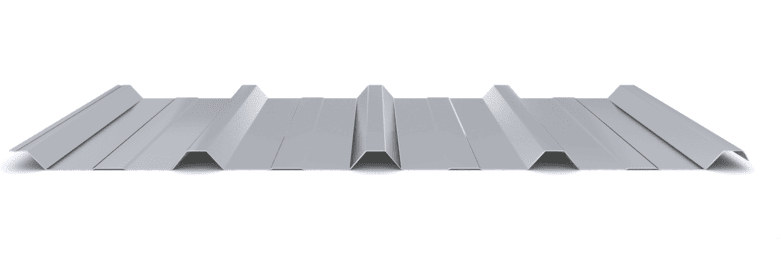
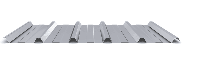
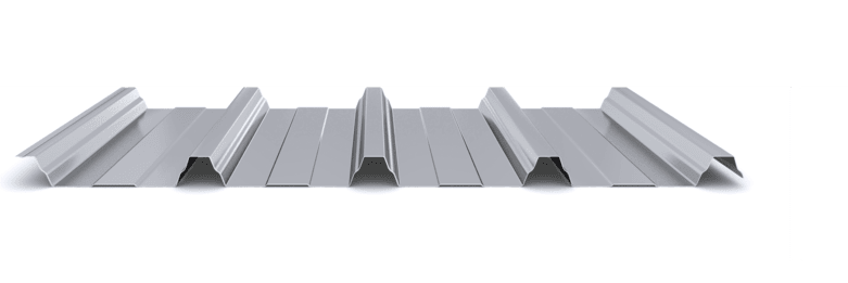
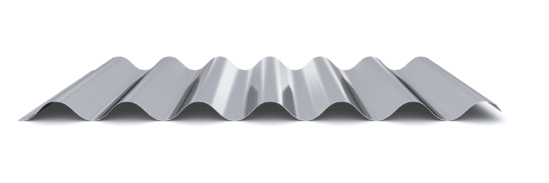
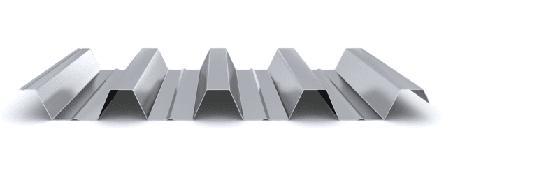
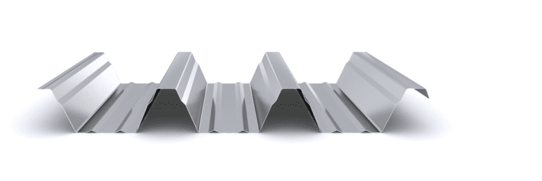
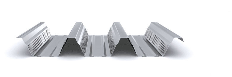
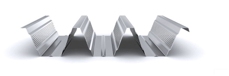
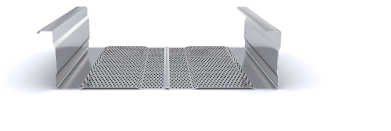
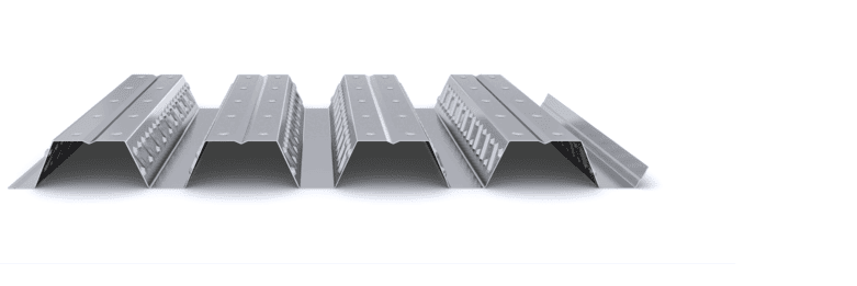
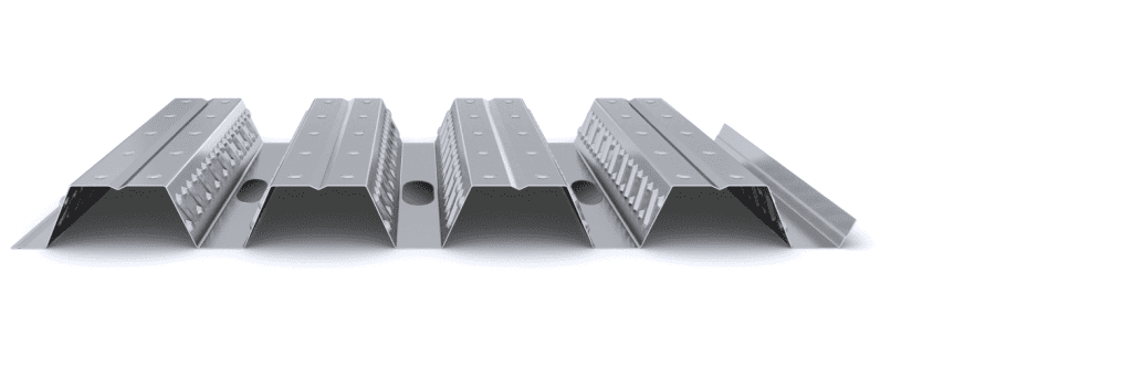
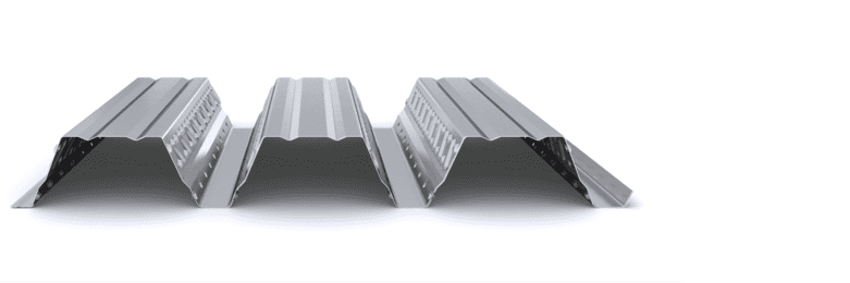
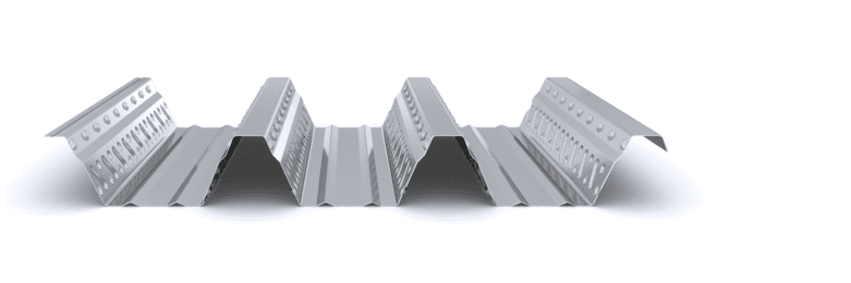
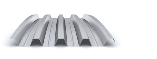
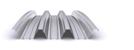
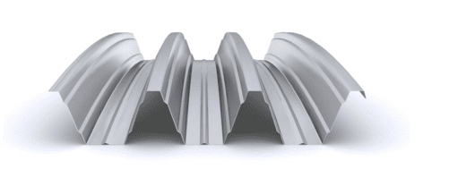
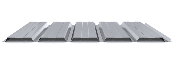
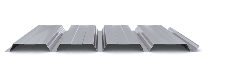
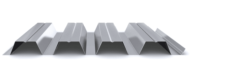
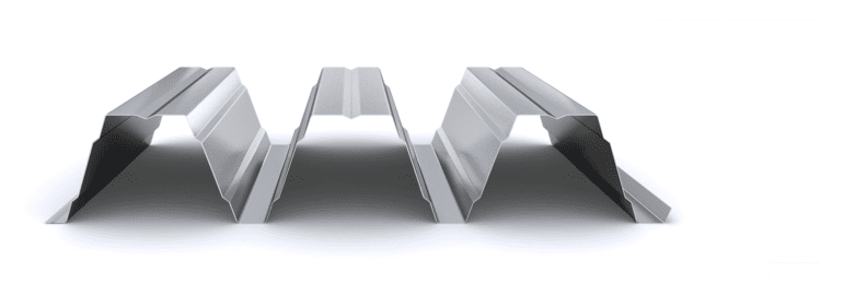
  • Types of composite profiles — INCO 70.4 Composite, INCO 100.3 Composite and INCO 100.3 R Composite — and the punched variant INCO 70.4 P Composite.
  • Composite profile thickness.
  • Base material of the sheet.
  • Types of concrete.
  • Upper and lower reinforcement.
  • Shear connectors where the project requires structural collaboration between the slab and the steel beams.

The selection and arrangement of these components influence structural behaviour, durability, construction and, where applicable, compliance with fire-resistance requirements.

5. Construction and structural details

The installation phase affects both safety during construction and the final behaviour of the system. This section currently covers the following topics:


  • Installation of the composite profile.
  • Fixings.
  • Minimum bearing requirements.
  • Composite floor system without propping.
  • Embedded in steel structures.
  • Cantilevers and openings.

These contents address both technical construction criteria and their impact on safety, erection sequence and site productivity.

6. Non-composite system

  • Permanent formwork using profiled steel sheet.

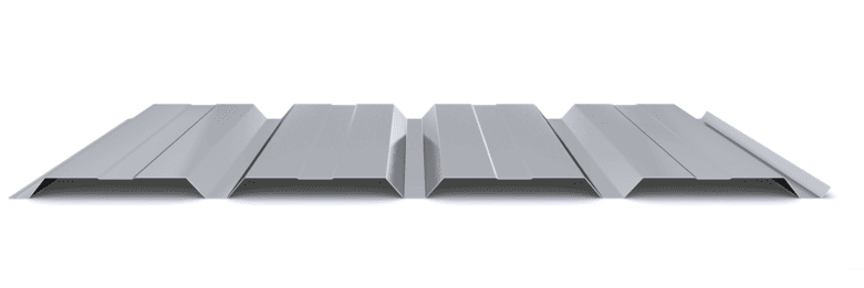
In certain projects, the profiled steel sheet is used as permanent formwork without considering its structural contribution to the concrete once hardened. This section establishes the differences between permanent formwork and composite floor systems, preventing the two systems from being confused during design, calculation or construction.

7. Calculation examples and structural optimisation

The calculation examples apply the criteria developed in the guide to specific configurations, making it possible to analyse how the main design variables influence the adopted solution.

This section includes case studies covering:


  • Long spans without propping.
  • High loads with moderate spans.
  • Design for high fire-resistance requirements.
  • Optimisation of slab depth and reinforcement.
  • Influence of support spacing.
  • Comparison of different span configurations and sheet layouts.

The results are technical and indicative in nature and must be supplemented by a project-specific calculation report.

Guide methodology

This Technical Guide can be consulted in three ways:


  1. Sequential reading by thematic sections.
  2. Specific consultation according to the project phase (preliminary design, calculation, construction).
  3. Consultation according to the determining design variable: span, loads, slab depth, fire resistance or construction conditions.

This organization makes it possible to adapt the consultation path to the profile of the specifier, designer, supervising engineer or construction manager. Each section links to specific articles that develop the relevant technical criteria, design variables and application examples.

Conclusion

The design of a composite floor system requires the integration of behaviour during both the formwork and composite phases, applicable regulatory requirements and actual construction conditions. The selection of the profile, slab depth, sheet thickness, support arrangement, propping and fire resistance must be analysed as a whole.

This Technical Guide organizes these criteria into an interconnected digital manual, supported by Incoperfil’s accumulated experience, the development of supporting calculation reports in accordance with the Eurocodes, and application examples that make it possible to apply calculation principles to specific project situations.

Incoperfil Technical Manual

For a complete definition of the system, design criteria, calculation bases, resistance tables, construction details, and installation procedures, consult the Incoperfil Composite Slab Technical Manual, available upon registration in the Documentation section of the website.


Last update: February 2026

© Incoperfil. All rights reserved.
The technical content of this article is part of the Composite Slab Technical Manual and the documentation registered by Incoperfil in ColorIURIS (Record No. 1-INCOPERFIL-12.2025).

Home / 0. Technical guide to composite slabs: design, calculation, components and installation

Guía técnica

23606

0. Technical guide to composite slabs: design, calculation, components and installation

This Technical Guide to composite slabs constitutes a structured manual for the design, calculation and execution of steel–concrete composite slabs with profiled decking. Its content is developed in accordance with Eurocodes 3 and 4, UNE-EN 1994-1-2 for fire resistance, and the current Structural Code.

The composite floor system is a mixed structural system in which the profiled steel sheet acts as load-bearing formwork during the construction phase and as tensile reinforcement for the composite section once the concrete has hardened. Its proper design requires the following aspects to be considered simultaneously: 
  • Behaviour during the formwork phase.
  • Behaviour during the composite phase.
  • Ultimate and serviceability limit states.
  • Fire resistance requirements.
  • Actual construction conditions.
This guide organizes these criteria into thematic sections, developed through interconnected individual articles, allowing for a structured and coherent consultation of the complete system.

Structure of the Technical Guide for Composite Floor Systems

1. General concepts of the system

This section introduces the definition of the composite system, its field of application, and the distinction between the element (profile/sheet) and the structural assembly (composite slab). 
  • Composite decking: definition, operation and applications.
  • Composite floor system: structural characteristics and fields of application.
  • Structural and construction advantages of the system.
These contents establish the necessary foundations for understanding the behaviour of the system before addressing its design and calculation.

2. Structural design of the composite floor system

The design of a composite floor system must address the formwork phase and the composite phase separately, identifying the variables that govern the solution in each project: span, loads, slab depth, fire resistance and construction conditions.This section brings together the fundamental design criteria: 
  • System phases: formwork and composite phase.
  • Structural design criteria.
  • Calculation using resistance tables and a supporting calculation report.
  • Spacing between supports.
  • Selection of the composite profile according to span, loads, slab depth, fire resistance and construction conditions.
  • Applicable standards (Eurocodes 3 and 4).
The objective is to provide a clear methodology for structuring decision-making from the preliminary design stage through to final verification.

3. Fire resistance of the composite floor system

The fire resistance of the composite floor system is verified in accordance with UNE-EN 1994-1-2 and depends mainly on: 
  • The total slab depth.
  • The position and concrete cover of the lower reinforcement.
  • The area of positive reinforcement and/or fire reinforcement, when required.
  • The geometry of the composite profile.
  • The loads acting under fire conditions.
This section develops the design and verification criteria for different REI requirements, as well as the influence of slab depth, reinforcement and profile type on the final solution.

4. Components of the composite slab

The structural performance of the system depends on the correct selection and coordination of its components: 
  • Types of composite profiles — INCO 70.4 Composite, INCO 100.3 Composite and INCO 100.3 R Composite — and the punched variant INCO 70.4 P Composite.
  • Composite profile thickness.
  • Base material of the sheet.
  • Types of concrete.
  • Upper and lower reinforcement.
  • Shear connectors where the project requires structural collaboration between the slab and the steel beams.
The selection and arrangement of these components influence structural behaviour, durability, construction and, where applicable, compliance with fire-resistance requirements.

5. Construction and structural details

The installation phase affects both safety during construction and the final behaviour of the system. This section currently covers the following topics: 
  • Installation of the composite profile.
  • Fixings.
  • Minimum bearing requirements.
  • Composite floor system without propping.
  • Embedded in steel structures.
  • Cantilevers and openings.
These contents address both technical construction criteria and their impact on safety, erection sequence and site productivity.

6. Non-composite system

  • Permanent formwork using profiled steel sheet.
In certain projects, the profiled steel sheet is used as permanent formwork without considering its structural contribution to the concrete once hardened. This section establishes the differences between permanent formwork and composite floor systems, preventing the two systems from being confused during design, calculation or construction.

7. Calculation examples and structural optimisation

The calculation examples apply the criteria developed in the guide to specific configurations, making it possible to analyse how the main design variables influence the adopted solution.This section includes case studies covering: 
  • Long spans without propping.
  • High loads with moderate spans.
  • Design for high fire-resistance requirements.
  • Optimisation of slab depth and reinforcement.
  • Influence of support spacing.
  • Comparison of different span configurations and sheet layouts.
The results are technical and indicative in nature and must be supplemented by a project-specific calculation report.

Guide methodology

This Technical Guide can be consulted in three ways: 
  1. Sequential reading by thematic sections.
  2. Specific consultation according to the project phase (preliminary design, calculation, construction).
  3. Consultation according to the determining design variable: span, loads, slab depth, fire resistance or construction conditions.
This organization makes it possible to adapt the consultation path to the profile of the specifier, designer, supervising engineer or construction manager. Each section links to specific articles that develop the relevant technical criteria, design variables and application examples.

Conclusion

The design of a composite floor system requires the integration of behaviour during both the formwork and composite phases, applicable regulatory requirements and actual construction conditions. The selection of the profile, slab depth, sheet thickness, support arrangement, propping and fire resistance must be analysed as a whole.This Technical Guide organizes these criteria into an interconnected digital manual, supported by Incoperfil’s accumulated experience, the development of supporting calculation reports in accordance with the Eurocodes, and application examples that make it possible to apply calculation principles to specific project situations.

Incoperfil Technical Manual

For a complete definition of the system, design criteria, calculation bases, resistance tables, construction details, and installation procedures, consult the Incoperfil Composite Slab Technical Manual, available upon registration in the Documentation section of the website.


Last update: February 2026

© Incoperfil. All rights reserved.
The technical content of this article is part of the Composite Slab Technical Manual and the documentation registered by Incoperfil in ColorIURIS (Record No. 1-INCOPERFIL-12.2025).