


The calculation of a composite floor is based on the composite behavior between steel and concrete, where the steel deck initially acts as formwork and, after the concrete has hardened, as tensile reinforcement. The reference standards — UNE-EN 1993-1-3 (Eurocode 3) and UNE-EN 1994-1-1 (Eurocode 4) — establish the design and verification criteria for both the construction phase and the composite phase, ensuring structural safety and compliance with ultimate and serviceability limit states.
This article describes the calculation stages and the available tools, from load tables to the preparation of a supporting structural calculation report.
How to calculate a composite floor: construction phase
During construction, the composite deck must support the weight of fresh concrete, construction loads, and the possible ponding effect. Dimensioning at this stage requires verification of the steel deck for:
Ultimate Limit States (ULS): bending resistance, shear resistance, and local buckling.
Serviceability Limit States (SLS): maximum deflection ≤ L/180 and ≤ 20 mm.
Ponding effect: when deflection caused by self-weight and concrete casting exceeds 1/10 of the slab depth, an additional load resulting from increased concrete thickness must be considered.
Construction loads adopted are those established by regulations:
0.75 kN/m² uniformly distributed.
0.75 kN/m² localized over a 3 m area at mid-span and over intermediate supports.
These checks ensure that the composite deck functions as stable and safe formwork, even in unpropped configurations.
How to calculate a composite floor: composite phase
Once the concrete has hardened, the profile and slab work together as a composite section. At this stage, the following verifications are carried out:
Ultimate Limit States (ULS): bending resistance, shear resistance, and longitudinal shear resistance.
Serviceability Limit States (SLS):
L ≤ 3,50 m → L/350
L > 3,50 m → L/700 + 5 mm
With brittle finishes → L/700 y L/1000 + 5 mm
Fire resistance (UNE-EN 1994-1-2): load-bearing capacity (R), integrity (E), and thermal insulation (I) are determined according to slab depth and specific bottom reinforcement for fire design. High fire classifications can be achieved without additional sprayed protection, depending on the configuration.
Use of load tables
The calculation tables for Incoperfil composite profiles provide a practical tool for preliminary estimation of load-bearing capacity prior to detailed structural analysis.
These tables are developed under the following load combination assumptions:
- ULS: Q = 1,35·PP + 1,50·SU
- SLS: Q = 1,00·PP + 1,00·SU
Where:
PP: self-weight of the floor (steel + concrete).
SU: live load (kN/m²).
The values depend on the deck thickness, slab depth, number of spans, and whether propping is used.
For guidance:
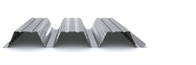
INCO 70.4 Composite: spans close to 4 m without propping in typical configurations.
INCO 100.3 Composite: spans close to 5 m without propping in certain configurations.
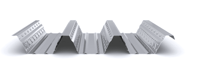
INCO 100.3 R Composite: solutions optimized for fire-resistance requirements with typical spans of around 4 m, subject to calculation.
The tables allow for preliminary selection of the most suitable profile, which must subsequently be verified through full structural calculation.
Indicative example of calculation using the tables
For a floor with the following conditions:
3.5 m span between supports (2 spans).
Live load = 5 kN/m².
Fire requirement REI 60.
INCO 100.3 Composite profile (1.00 mm thickness).
Based on the tables, a solution compatible with the specified requirements can be preselected and must then be confirmed through full structural verification.
Result: the floor complies without propping with a total slab depth of 160 mm, welded mesh 15x15x8, positive reinforcement Ø8 mm (REI 60), and a live load capacity of 784 kg/m².
Composite floor calculation report
For final justification, a structural calculation report is prepared in accordance with UNE-EN 1993-1-3, UNE-EN 1994-1-1, and UNE-EN 1994-1-2, verifying limit states, deflections, and fire resistance.
The calculation report request requires the following basic data:
Span between supports.
Live load and permanent loads.
Fire-resistance requirement (REI).
Type of supporting structure.
Construction condition with or without propping.
Based on this information, the optimal solution is determined and the corresponding technical justification is issued. Access the composite floor calculation form.
Conclusion
The calculation of a composite floor is carried out in two phases — construction (formwork) phase and composite phase — and requires verification of limit states, deflections, and fire resistance in accordance with European standards. Load tables allow for an effective preliminary estimation, while the technical report ensures full structural validation for each project.
Incoperfil technical manual
For a complete definition of the system, design criteria, calculation bases, resistance tables, construction details, and installation procedures, consult the Incoperfil Composite Slab Technical Manual, available upon registration in the Documentation section of the website.
Last update: February 2026
© Incoperfil. All rights reserved.
The technical content of this article forms part of the Composite Flooring Technical Manual and the documentation registered by Incoperfil with ColorURIS (Act No. 1-INCOPERFIL-12.2025).