


The spacing between supports is one of the most determining parameters in composite floor design, as it affects load-bearing capacity, total slab depth, and the possible need for propping during construction. In structural design, the center-to-center distance between beams is considered, and maintaining a uniform layout is recommended to optimize overall floor performance.
Influence of Main Factors
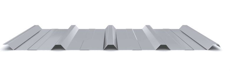
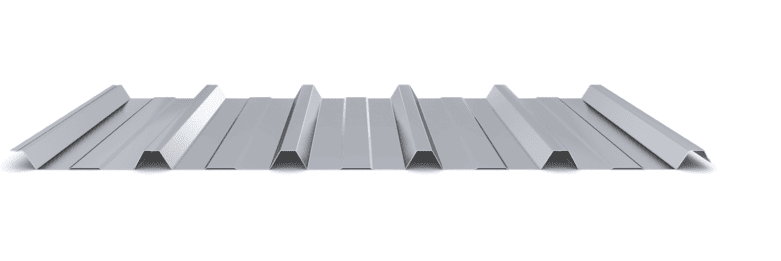
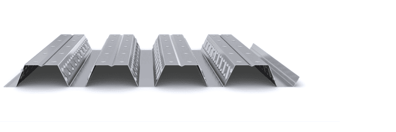
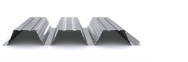
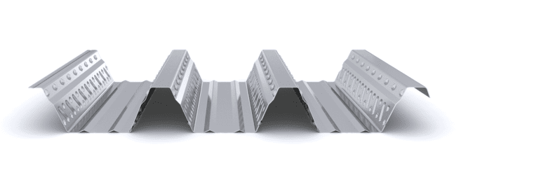
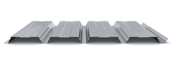
- Type and Depth of the Composite Profile
Profiles with greater rib depth, such as INCO 100.3 Composite, allow larger support spacing without propping in certain configurations. INCO 70.4 Composite is suitable for shallower slabs, where support spacing is generally more limited. - Deck Thickness
Increasing deck thickness improves load-bearing capacity during the construction phase and may allow greater spacing between supports, subject to structural verification. - Total Slab Depth
Greater slab depth increases stiffness and load-bearing capacity, facilitating longer spans between supports - Number of Spans
Continuous multi-span floors with uniform spacing optimize bending moment distribution and generally provide better performance than simply supported configurations or unequal spans - Presence of Propping
The use of intermediate props during concreting reduces the effective working span of the deck and expands the allowable support spacing during construction.
Indicative Application Ranges
For reference, the load tables in the IncoPerfil Composite Flooring Technical Manual show that typical spans in unpropped solutions generally range between 2 and 5 meters, depending on the selected profile, slab depth, and design loads.
For a slab depth of 120 mm (2 spans), the following may be considered for guidance:
2,0 m → very high load level → 30 kN/m²
3,0 m → high load level → 12 kN/m²
4,0 m → medium load level → 6 kN/m²
5,0 m → low load level → 3 kN/m²
For a slab depth of 200 mm (2 spans), allowable load levels increase for the same support spacing:
2,0 m → very high load level → 50 kN/m²
3,0 m → very high load level → 20 kN/m²
4,0 m → high load level → 10 kN/m²
5,0 m → medium load level → 5 kN/m²
These values are indicative and correspond to specific calculation configurations. The final solution must be justified through a structural calculation report in accordance with applicable standards.
Design Recommendations
Support spacing should be defined by seeking a balance between stiffness, span, and live loads.
Maintain uniform spacing, preferably between 2 and 3 meters, when pursuing an optimized solution in terms of slab depth and material consumption.
Adjust spacing according to the expected loads and available slab depth.
Avoid spacings greater than 5 meters in standard solutions, as this represents the maximum tested limit of the system. Larger spans require specific verification through structural calculation.
Always consider total slab depth as a key variable when defining beam spacing.
Conclusion
The spacing between supports in composite flooring directly influences its structural behavior, required slab depth, and the need for propping during construction. Proper definition of this parameter, coordinated with the selected profile and project loads, enables efficient, safe, and technically optimized solutions.
Incoperfil Technical Manual
For a complete definition of the system, design criteria, calculation bases, resistance tables, construction details, and installation procedures, consult the Incoperfil Composite Slab Technical Manual, available upon registration in the Documentation section of the website.
Last update: February 2026
© Incoperfil. All rights reserved.
The technical content of this article forms part of the Composite Flooring Technical Manual and the documentation registered by Incoperfil with ColorURIS (Act No. 1-INCOPERFIL-12.2025).