Request a
calculation form

Home / Profiles / Composite floor deck / INCO 70.4 P Composite

INCO 70.4 P Composite

  • Composite floor deck
  • Cover width: 840 mm
  • Profile depth: 70 mm
  • Profile pitch: 210 mm

Geometry

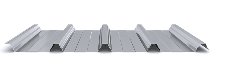
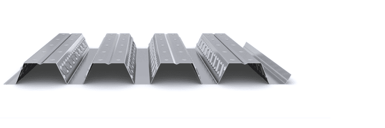
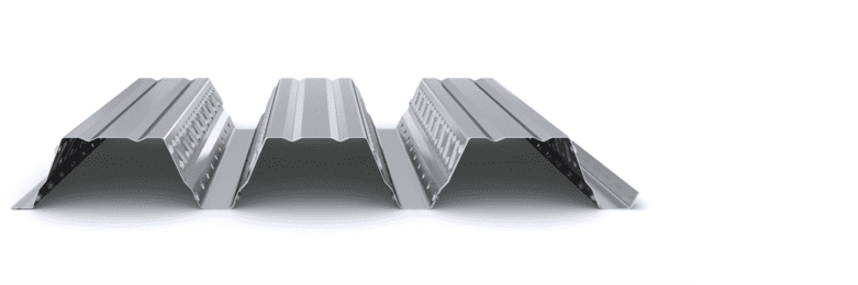
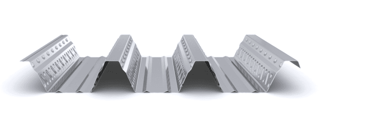
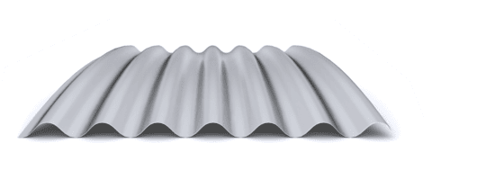
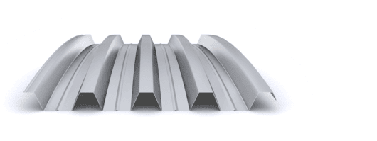
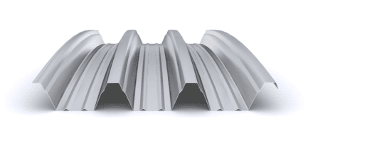
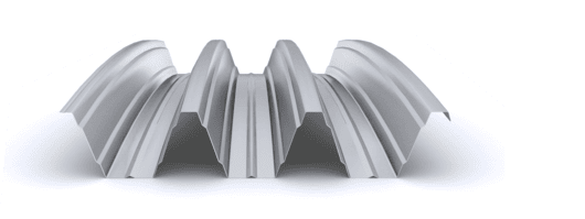
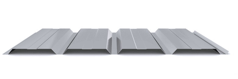
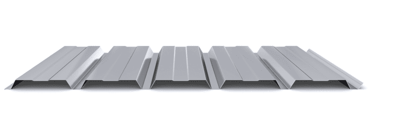
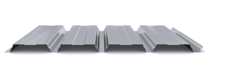
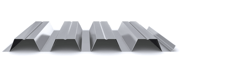
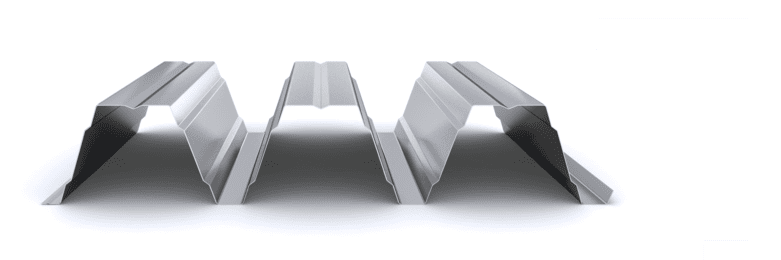
The INCO 70.4 composite profile is used as a composite steel deck, together with concrete, to form floor slab structures in industrial buildings, administrative buildings, residential constructions, and other types of buildings. It offers excellent performance within composite slab solutions, with an effective width of 840 mm, a rib height of 70 mm, and a rib spacing of 210 mm.

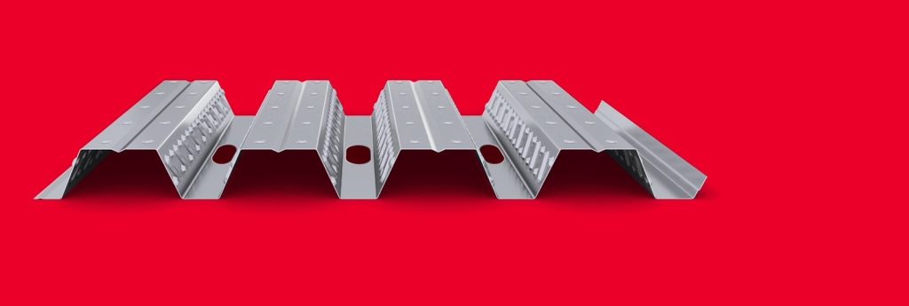
The perforations in the composite profile allow the passage of cylindrical connectors (Nelson type) previously welded to the beams.

The composite profile performs a dual function: it acts as permanent formwork during the concrete pouring phase, achieving spans of up to 4 m without the need for temporary propping, and as positive reinforcement in the composite phase, ensuring that the slab can reach spans of up to 5 m. It is especially designed to provide slab systems with a minimum total depth of 120 mm, including a 70 mm rib height and a 50 mm concrete topping.

QB03

It is available in both galvanized steel and Magnelis-coated steel.


  • Maximum free height between slabs
  • Without shoring up to 4 m
  • Total slab thickness from 110 mm
  • Up to 2.000 m²/ transport
  • With certification QB03 number 03-0002-335-960
  • Min/max manufacturing length: 2 /12 m
  • Thickness range: 0,80 | 1,00 | 1,20 mm
  • Minimum order: 250 m²
  • Package weight: 1.500 – 2.000 kg
  • Galvanized steel (Z200) Others on request
  • Magnelis steel (ZM310). Others on request

Projects

Start designing yout project

Request calculation report

Complete the form below to receive a detailed report justifying the most suitable enclosure profile. You will receive the information as soon as possible.

Building characteristics
Industrial roof application loads
(1) For sections of the roof profile with 2, 3, 4 or more supports, indicate the greatest distances between supports that appear in your project.
Type of environment
Attached documentation
Additional comments
Contact information
Project data
Building characteristics
Application loads for the industrial facade
(1) For sections of the façade profile with 2, 3, 4 or more supports, indicate the greatest distances between supports that are presented in your project.
Type of environment
Attached documentation
Additional comments
Contact information
Project data
Building characteristics
Deck loads
(1) For sections of the roof profile with 2, 3, 4 or more supports, indicate the greatest distances between supports that appear in your project.
Type of environment
Attached documentation
Additional comments
Contact information
Project data
Structure features
Composite slab characteristics
(1) For the sections of the composite slab with 2, 3, 4 or more supports, indicate the greatest distances between supports that appear in your project. Span length < 5,00 m.
Type of environment
Attached documentation
Additional comments
Contact information
Project data
Building characteristics
Characteristics of the facade
Roof typology

(1) Indicate the length of the span of the arch, which is the greatest horizontal distance between the supports of the curved roofing.

(2) Plan-view dimension representing the full length of the curved roof measured perpendicular to the arch span.

(3) Specify the obstructed area under the canopy, in square meters, as a proportion of the total area of the front or side (transverse or longitudinal) façade, in order to calculate the obstruction factor. If it is a closed construction or there is no obstruction area, indicate 0 m².

Environment characteristics
Type of environment
Attached documentation
Additional comments
Contact information
Project data

Latest projects