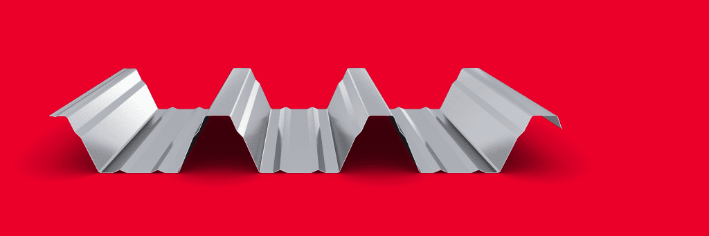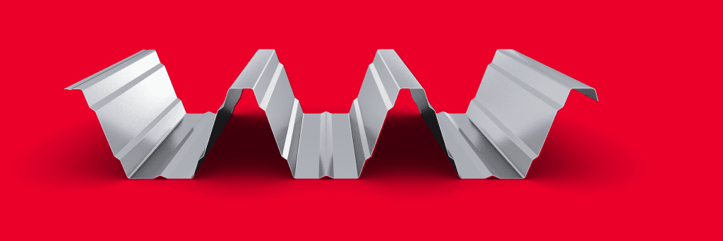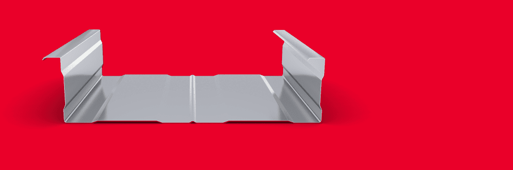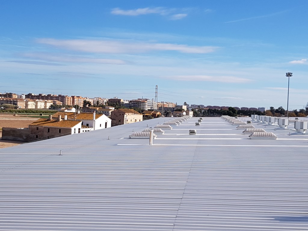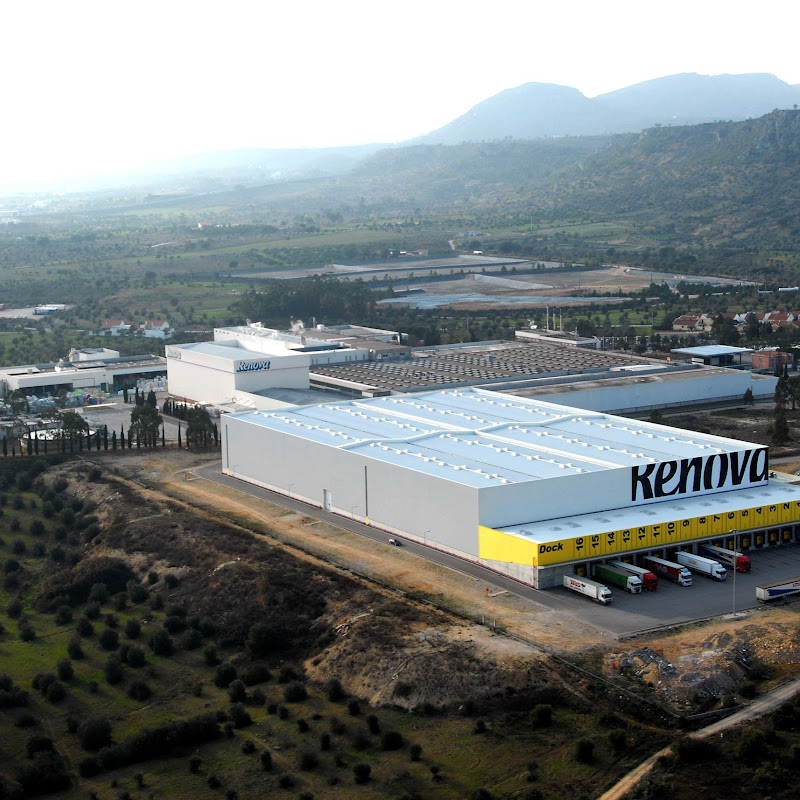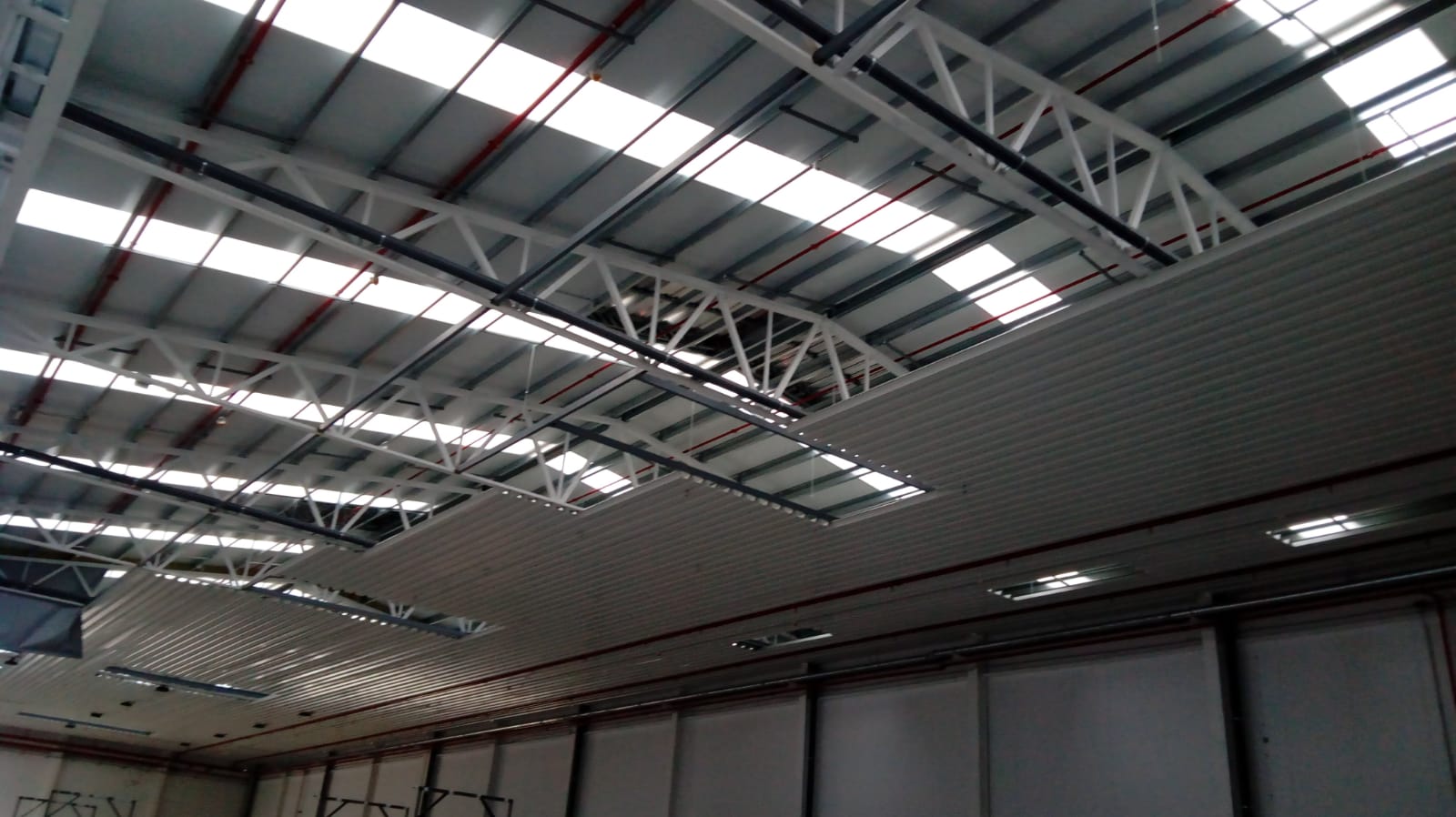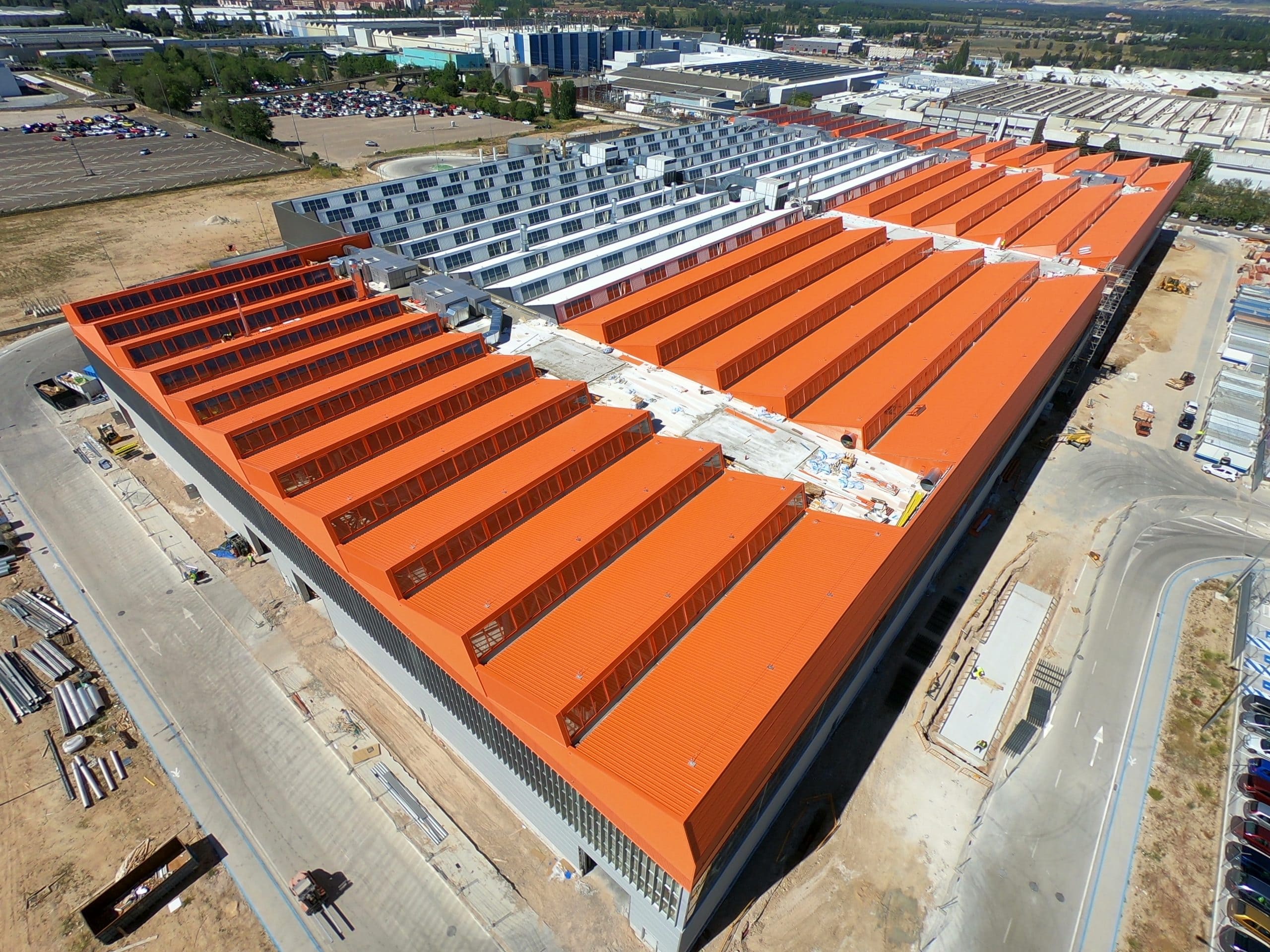
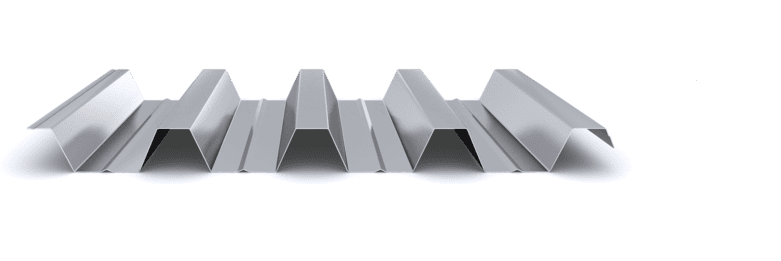
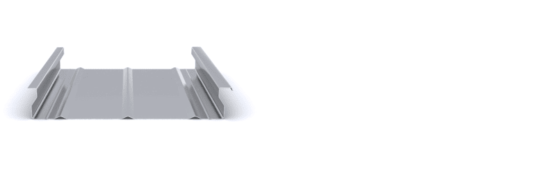
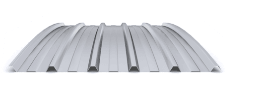
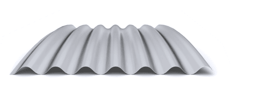
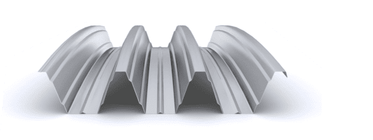
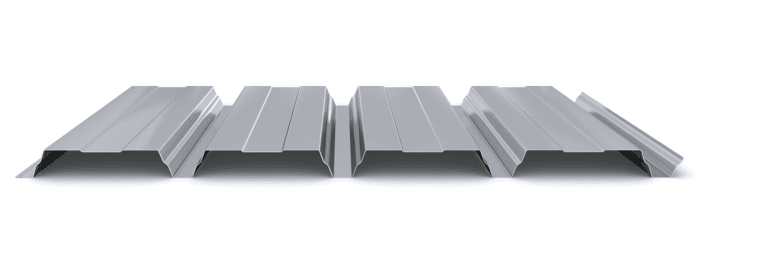
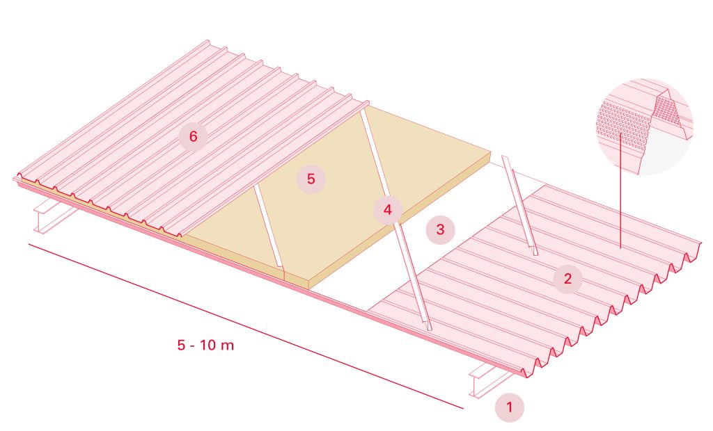
The self-supporting multi-layer industrial roof is made up of a corrugated outer covering profile, which acts as a sealing element, and a corrugated profile or inner support tray that performs the resistant function. Both profiles are fixed to each other using the separator profile, which maintains the necessary distance to accommodate the insulation and vapor barrier. Its main function is to provide a watertight closure in constructions that require thermal conditioning of the interior.
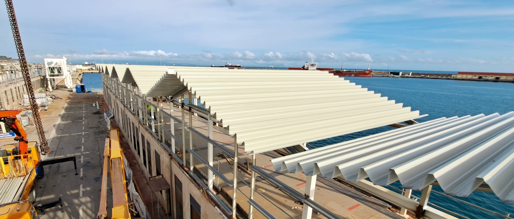
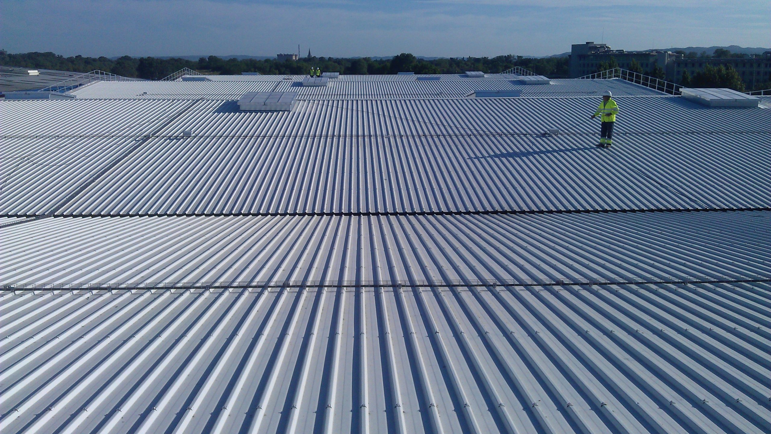
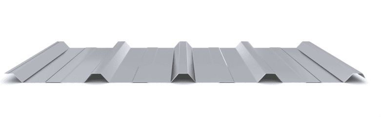
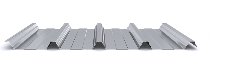
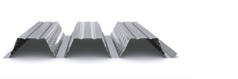
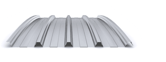
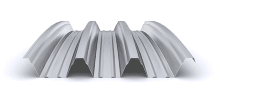
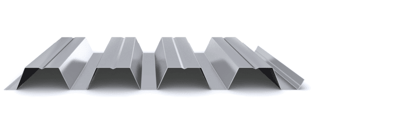
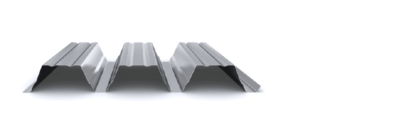
The corrugated profile of the exterior cladding will meet the mechanical requirements specified in the project and will also guarantee the watertightness of the roof. The interior self-supporting ribbed profile will mainly comply with the mechanical requirements specified in the project. This interior support profile will be installed on the main structural structure, which is generally composed of metal, concrete or wooden frames. The main advantage of this system is the elimination of the secondary structure or purlins, since the support profile can reach spans of up to 10 meters between supports, as is the case of the INCO 155.3 profile. By dispensing with the secondary structure, the installation performance of the deck roofi is considerably improved. Furthermore, this support profile serves as both a working platform and a bracing element for the structure.
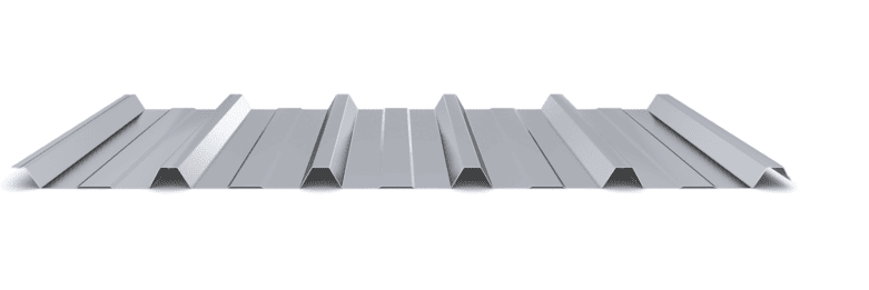
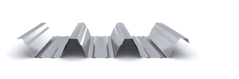
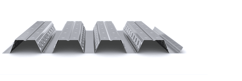
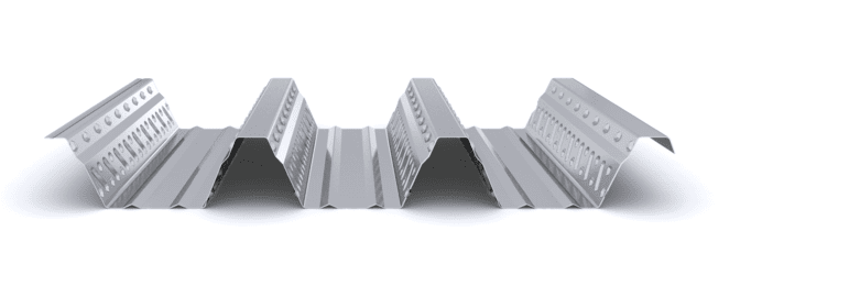
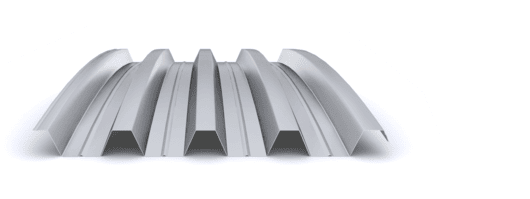
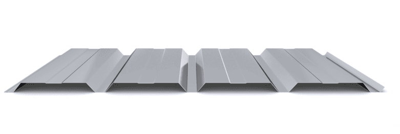
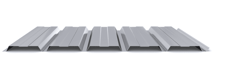
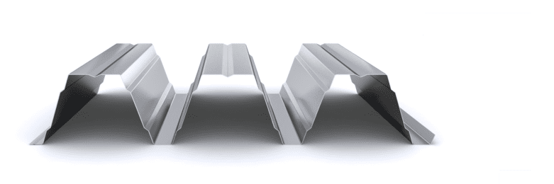
In those rooms where it is necessary to improve acoustic comfort, solutions can be used with the micro-perforated interior support trapezoidal profile, to increase the acoustic absorption of the deck roof. These perforations can be made in the webs of the profile in profiles with a large depth, or throughout its surface in profiles with a reduced depth. Typically, drilling of type R5T8 is used for perforations in the webs and type R3T6 for perforations throughout the surface.
Minimum Slopes
The simple roof must have a minimum slope towards the water evacuation elements greater than that specified in the CTE DB HS Health. Table 2.10 Inclined roof slopes, depending on the profile depth of each profile.
Said table adapted to the exterior cladding profiles manufactured by Incoperfil would be the following:
| PROFILE | TYPE | MINIMUM SLOPE |
| INCO 30.4 | Trapezoidal | 10% |
| INCO 30.5 | Trapezoidal | 10% |
| INCO 44.4 | Trapezoidal | 8% |
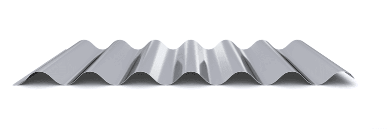
| INCO 44.6 | Wavy | 10% |
| INCO 70.4 | Trapezoidal | 5% |
Slopes on inclined roofs with galvanized profiles according to CTE DB HS Health.