Request a
calculation form

Home / Systems / Industrial roofing system

Industrial roofing system

Use our range of metal profiles and trays to design multi-layer roof systems that adapt to the thermal and acoustic needs of the project efficiently, whether it is new construction or rehabilitation.
  • Lightweight and strong roof solutions
  • Versatile multilayer systems to meet all regulatory requirements
  • The perforated interior profiles will allow you to maximize acoustic comfort
  • Select the appropriate coating to ensure the durability of the roofing based on the indoor and outdoor environment
  • Request technical support and calculation reports specific to your project

Self-supporting multilayer roofing

The multi-layer self-supporting roof is a construction solution in which there is no secondary support structure; the metal support profile acts as a resistant element, allowing the use of the most appropriate insulation for the project between its layers.

1. Principal structure
2. Steel roof decking
3. Vapor barrier
4. Separator profile
5. Isolation
6. Cladding profile

Simple industrial roofing

Combine speed and economy when isolation is not a condition.

Multilayer industrial roofing

Adapt the roofing to the most demanding thermal and acoustic requirements

Roof rehabilitation

Renovate a simple roof while ensuring watertightness and improving its thermal and acoustic insulation.

Related information

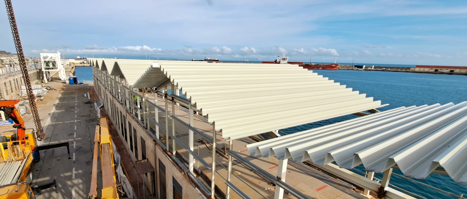
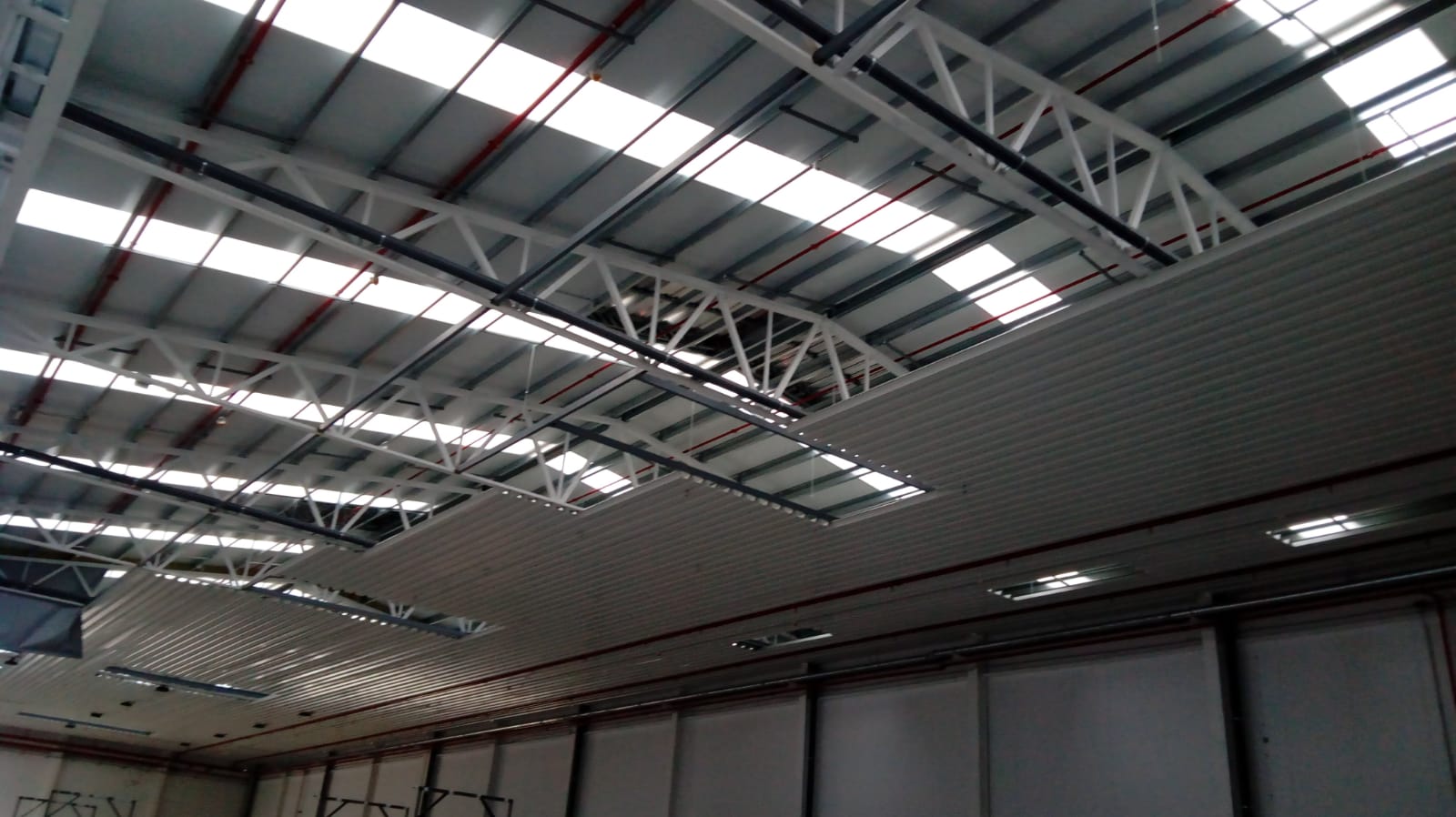
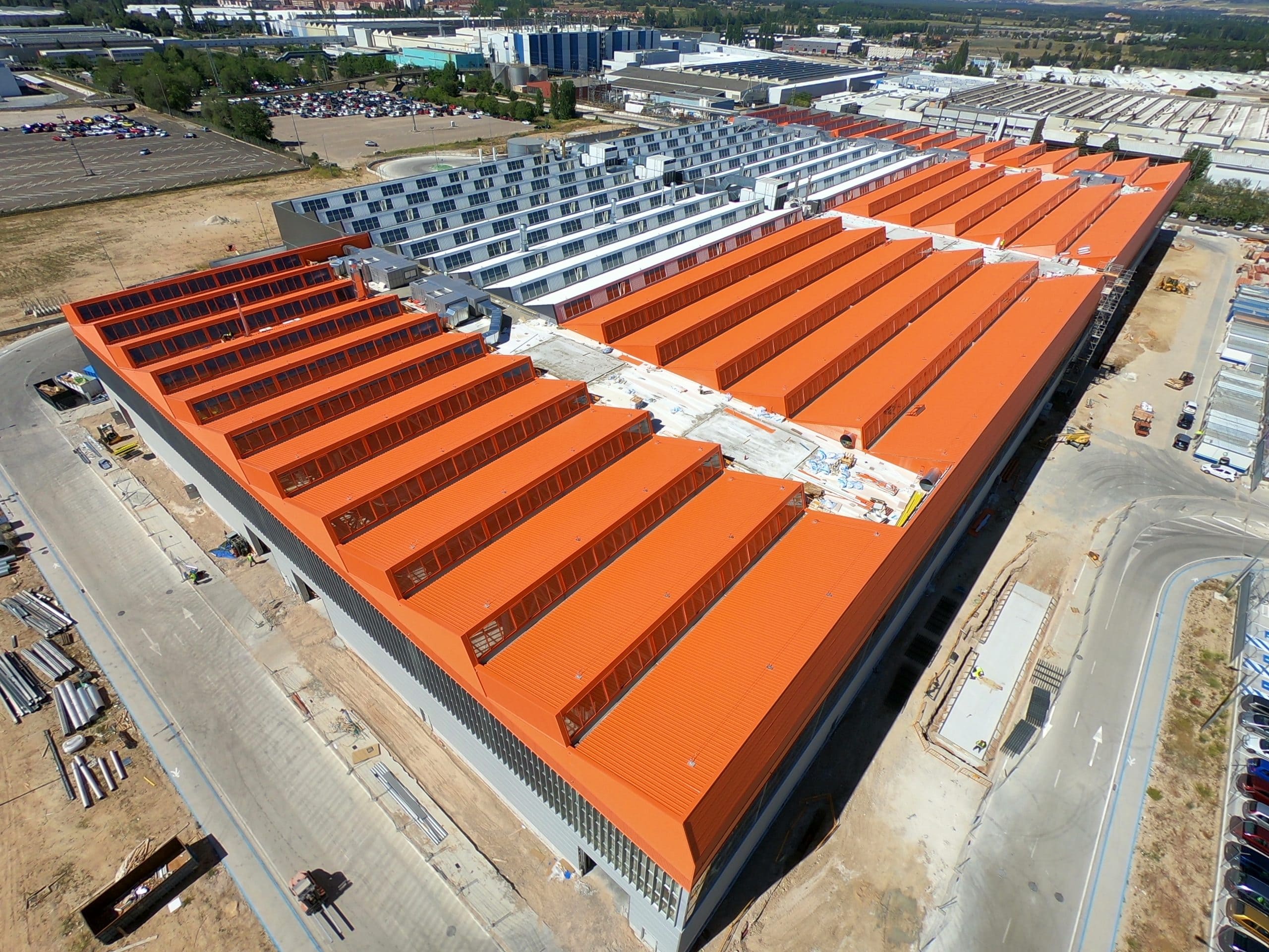
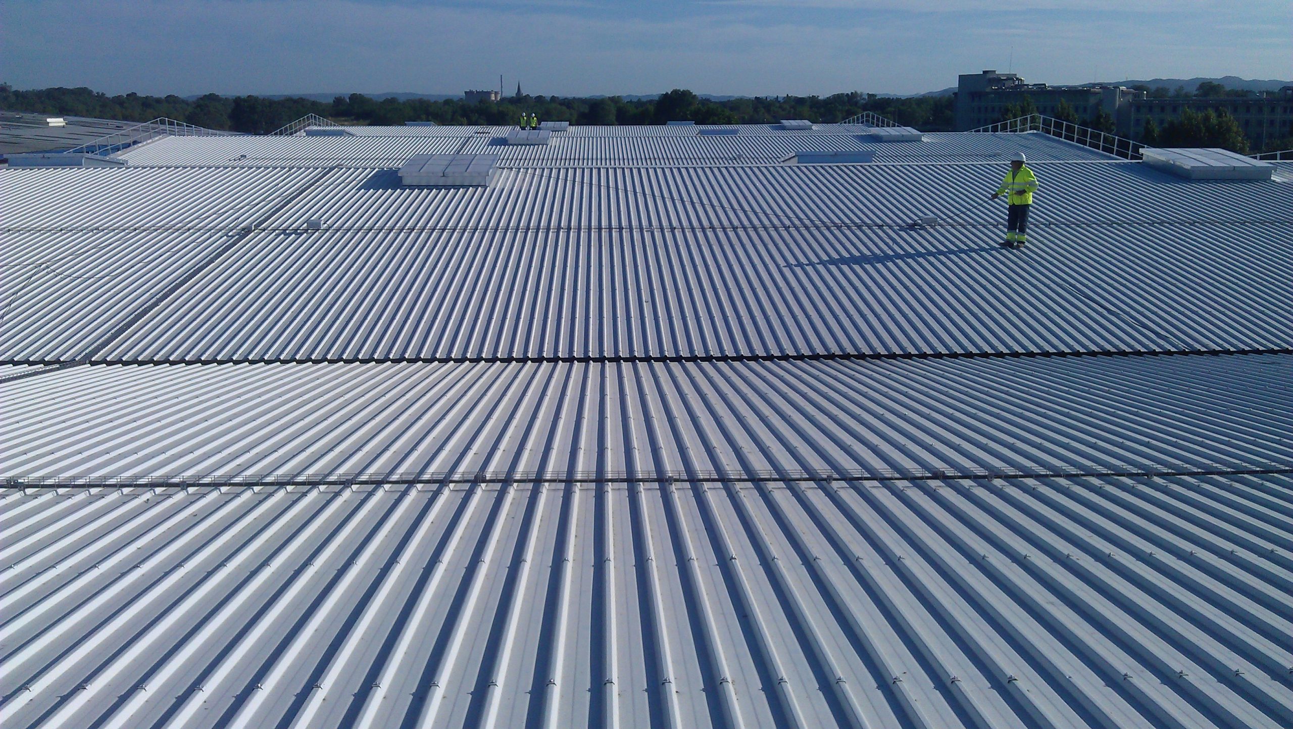
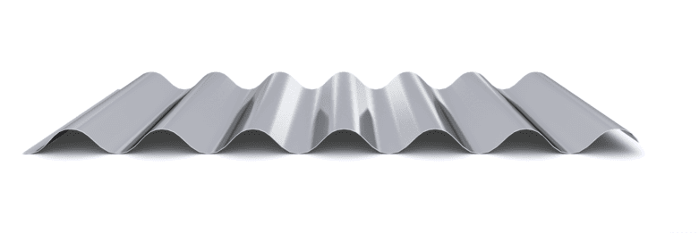
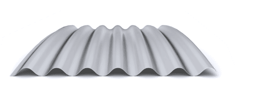
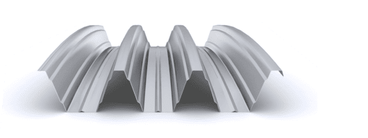
The industrial roof can be proposed using a simple solution, composed of a single corrugated profile, or a multi-layer, composed of a corrugated profile for the exterior roofing, a corrugated profile/inner tray and intermediate insulation.

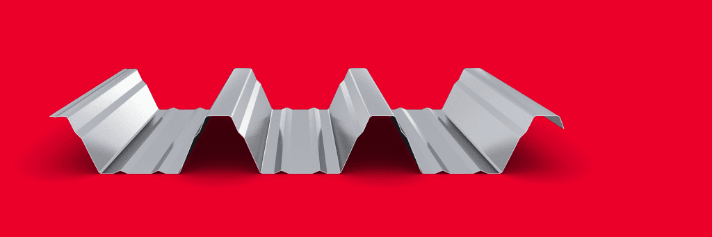
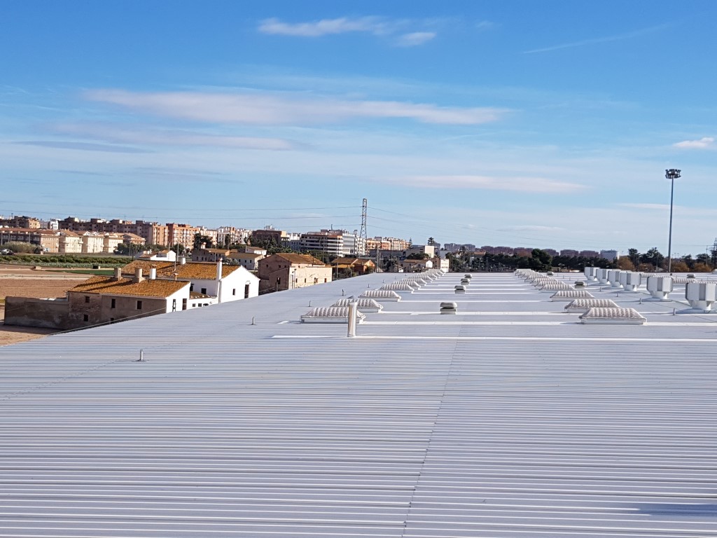
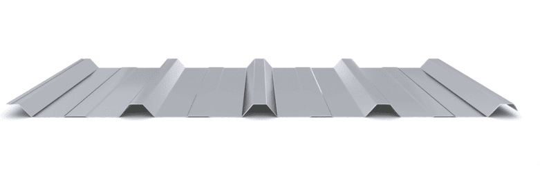
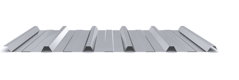
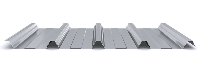
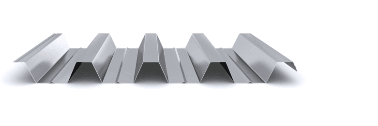
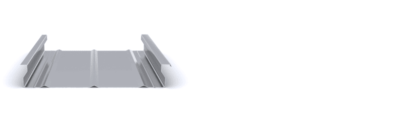
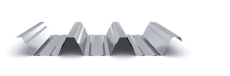
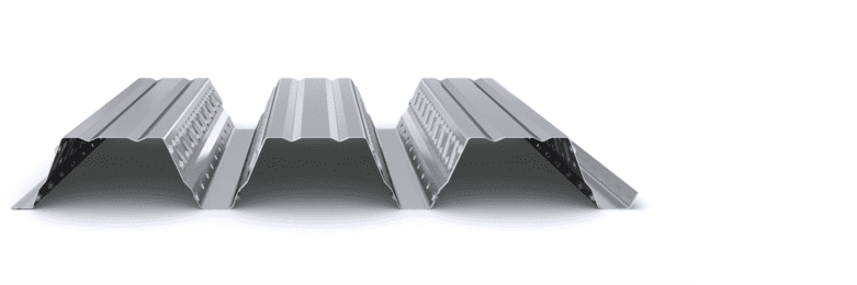
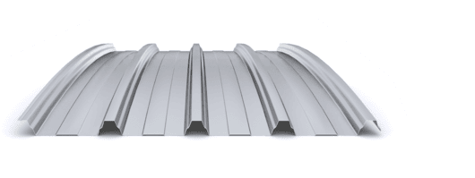
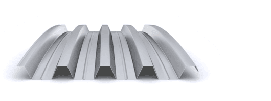
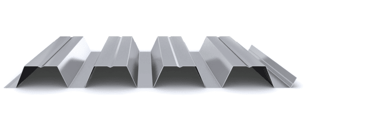
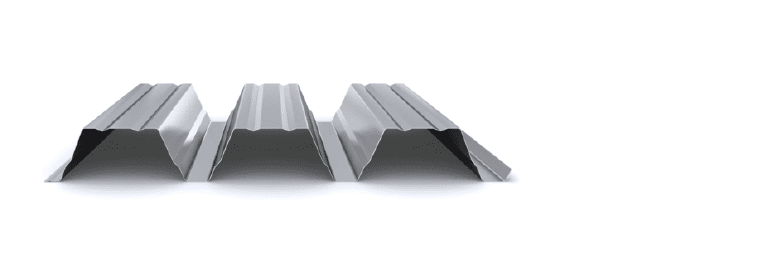
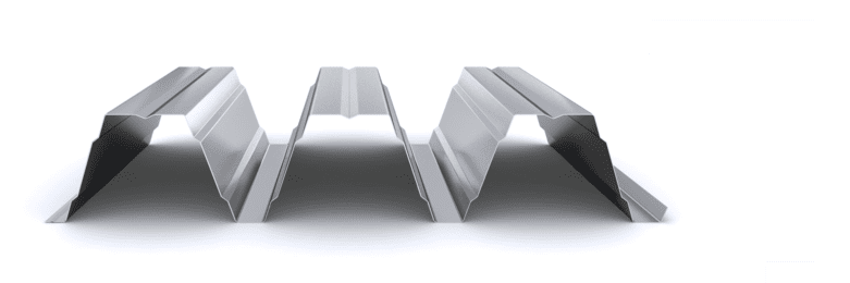
The simple industrial roof solution is made up of a trapezoidal profile that serves both as a sealing element and as support for the actions to which it is subjected. Its use is limited to canopies or closed spaces that do not require thermal and acoustic conditioning.

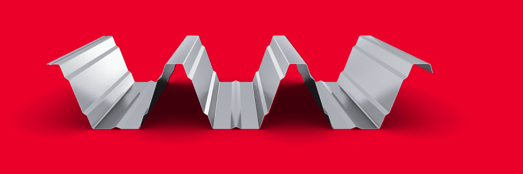
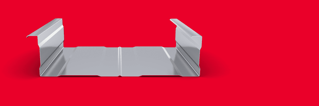
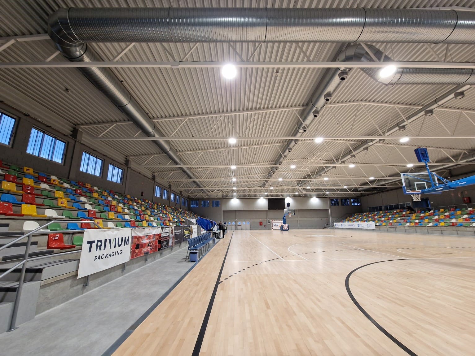
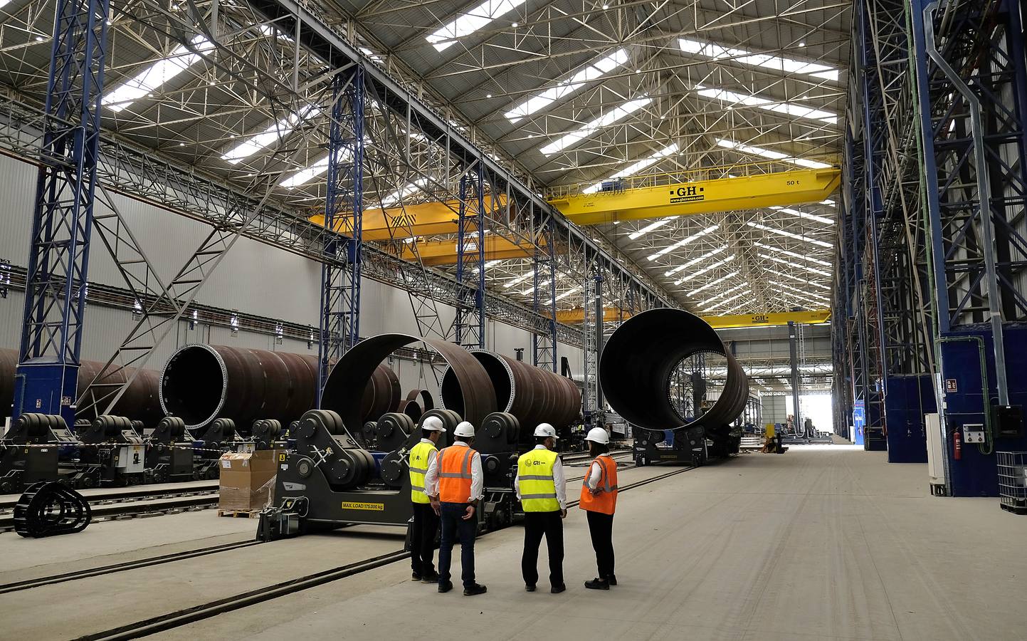
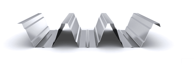
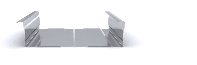
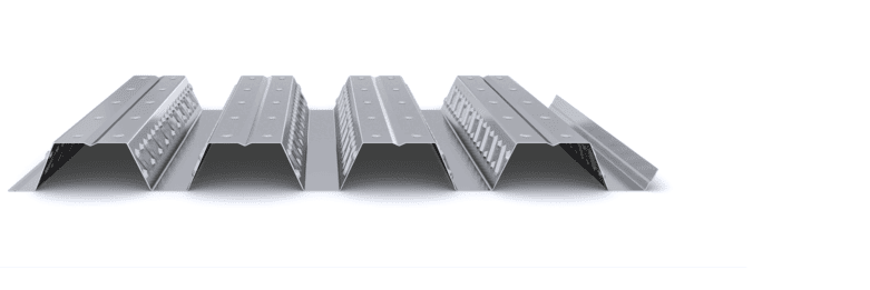
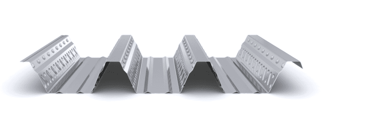
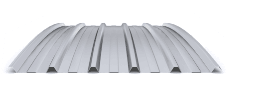
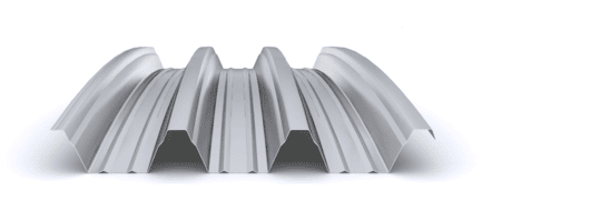
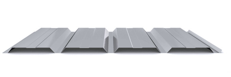
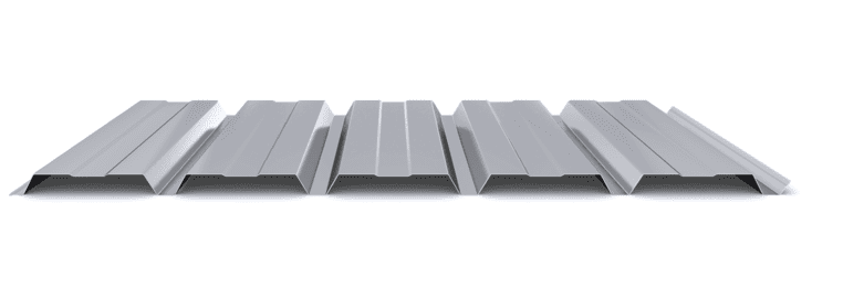
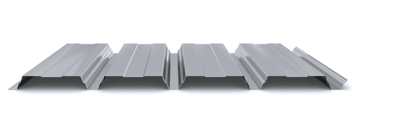
The multi-layer industrial roof solution is made up of a trapezoidal outer profile, which serves as a sealing element, and a corrugated profile/inner support tray, which performs the resistant function against external actions and the self-weight of the rest. of roof components: vapor barrier, thermal-acoustic insulation, separator profile and trapezoidal inner profile. This solution is used in closed spaces with thermal and acoustic conditioning needs.

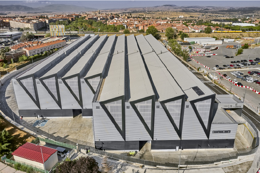
These solutions allow the construction of roofs with slopes between 5% and 10%, depending on the type of profile, with slopes greater than 10% being recommended.

  1. The main structure, formed by frames every 5-10 m, is responsible for supporting the main actions of the roof, guaranteeing its integrity and stability.
  2. The interior support profile constitutes the first layer of the roof enclosure and is placed and fixed on the main structure. This element supports both the own weight of the other components and the loads acting on the cover, meeting the corresponding mechanical requirements.
  3. The vapor barrier regulates vapor diffusion to prevent condensation and protect the insulation, thus improving energy efficiency and interior comfort.
  4. The separator profile, composed of Z-type profiles, is arranged on the interior support profile, fulfilling a double function: it provides space for insulation and allows the fixation of the exterior cladding profile.
  5. Thermal insulation, mainly rock wool, contributes significantly to energy savings and improves thermal and acoustic comfort inside the building.
  6. The exterior cladding profile constitutes the last layer of the roof enclosure and is placed and fixed on the separator profile. Its main function is to ensure watertightness and proper drainage of the roof.

Sketch of multi-layer self-supporting roof system - diagram

SYSTEM COMPONENTSSYSTEM ACCESSORIES
1.- Interior trapezoidal profilea.-Trimming | Side Wall Flashing
2.-Substructure | Omega Profileb.- Trimming | Ridge Cap Flashing
3.- Insulationc.-Element Sealing | Upper Joint
4.- Exterior trapezoidal profiled.- Trimming | Sandwich Roofing Closure
e.- Trimming | Extreme Gutter
f.- Element Sealing | Upper Joint
  • Industrial: Warehouses and production centers
  • Logistics Center: Warehouses and distribution centers
  • Commercial: Canopies, offices and commercial surfaces
  • Infrastructure: Stations and airports
  • Public: Schools, markets and hospitals
  • Sports: Stands, sports courts and pavilions
  • Agricultural: Stables, farms and sheds
  • Packaging and transportation: The industrial roof profiles are grouped in strapped packages of 20-25 sheets, with a maximum length depending on the type of profile and a maximum weight of 1.500 kg. Each package includes an identification label with details of the manufactured product, order and destination. Transportation is preferably carried out in a truck closed with a tarp to prevent the material from being exposed to the elements.
  • Reception and unloading: Before unloading, it is verified that the material matches the geometry and thickness specified in the project. Unloading is carried out with the appropriate lifting means, and preferably directly in the installation area, to minimize movements on site.
  • Storage and protection: On site, the packages are stored in a covered and ventilated area on inclined wooden sleepers and are protected from humidity with breathable tarps. Packages are not stacked more than three high and no other materials are placed on them.
  • Installation on the structure: The packages are placed on the main beams, close to the supports, ensuring that the structure can support their weight. They are oriented in the direction of installation and are placed manually, sheet by sheet, under the supervision of the Construction Management. In the case of large pieces, the sheets are individually lifted from the ground to their position on the roof.

Featured Products

  • Efficient and rigid
  • Self-supporting up to 7 m
  • Thickness: 0,6 – 1,5 mm
  • Up to 2.900 m² / transport
  • Exceptional resistance
  • Self-supporting up to 10 m
  • Thickness: 0,6 – 1,5 mm
  • Up to 2.400 m² / transport
  • Smooth interior finishes
  • Self-supporting up to 6 m
  • Thickness: 0,7 – 1,5 mm
  • Up to 500 m² / transport

Projects

Start designing yout project

Request calculation report

Complete the form below to receive a detailed report justifying the most suitable enclosure profile. You will receive the information as soon as possible.

Building characteristics
Industrial roof application loads
(1) For sections of the roof profile with 2, 3, 4 or more supports, indicate the greatest distances between supports that appear in your project.
Type of environment
Attached documentation
Additional comments
Contact information
Project data
Building characteristics
Application loads for the industrial facade
(1) For sections of the façade profile with 2, 3, 4 or more supports, indicate the greatest distances between supports that are presented in your project.
Type of environment
Attached documentation
Additional comments
Contact information
Project data
Building characteristics
Deck loads
(1) For sections of the roof profile with 2, 3, 4 or more supports, indicate the greatest distances between supports that appear in your project.
Type of environment
Attached documentation
Additional comments
Contact information
Project data
Structure features
Composite slab characteristics
(1) For the sections of the composite slab with 2, 3, 4 or more supports, indicate the greatest distances between supports that appear in your project. Span length < 5,00 m.
Type of environment
Attached documentation
Additional comments
Contact information
Project data
Building characteristics
Characteristics of the facade
Roof typology

(1) Indicate the length of the span of the arch, which is the greatest horizontal distance between the supports of the curved roofing.

(2) Plan-view dimension representing the full length of the curved roof measured perpendicular to the arch span.

(3) Specify the obstructed area under the canopy, in square meters, as a proportion of the total area of the front or side (transverse or longitudinal) façade, in order to calculate the obstruction factor. If it is a closed construction or there is no obstruction area, indicate 0 m².

Environment characteristics
Type of environment
Attached documentation
Additional comments
Contact information
Project data

Latest projects