Request a
calculation form

Home / Solutions / Permanent non-composite formwork profiles

Permanent non-composite formwork profiles

Croquis sistema encofrado perdido - esquema

The permanent formwork (non- composite formwork) uses a trapezoidal profile that acts as formwork executed on site

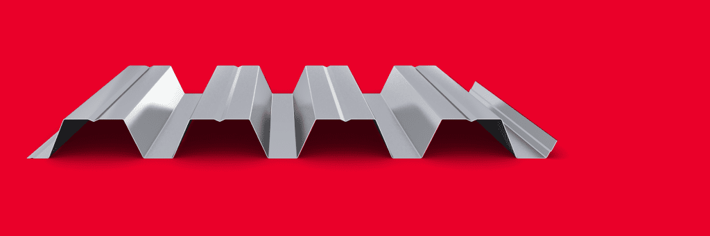
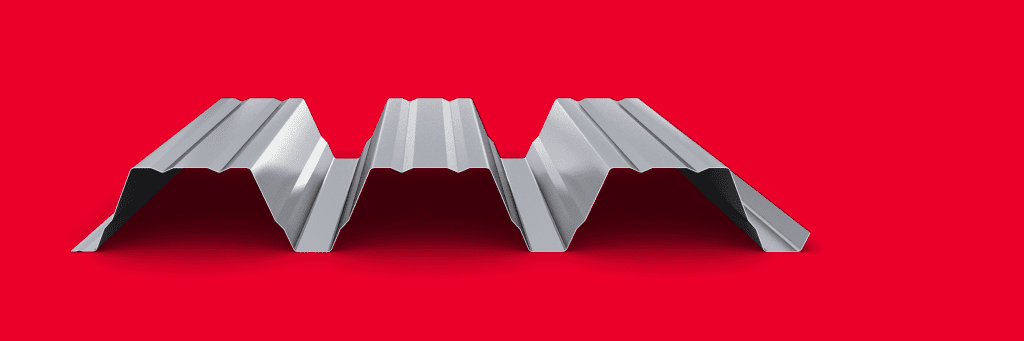
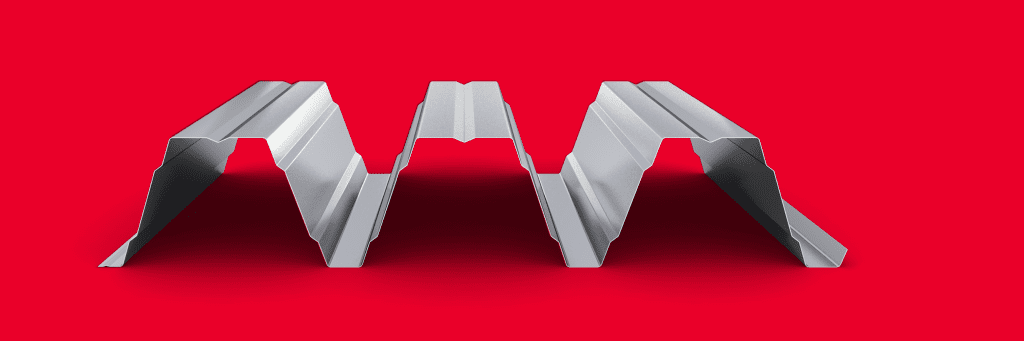
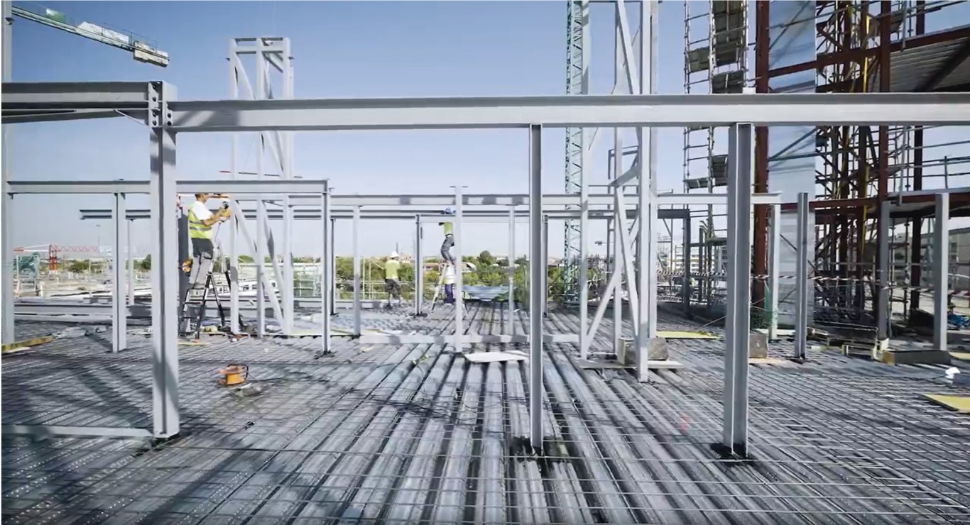
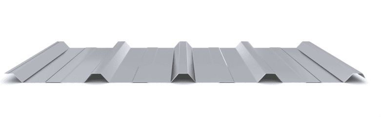
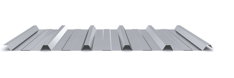
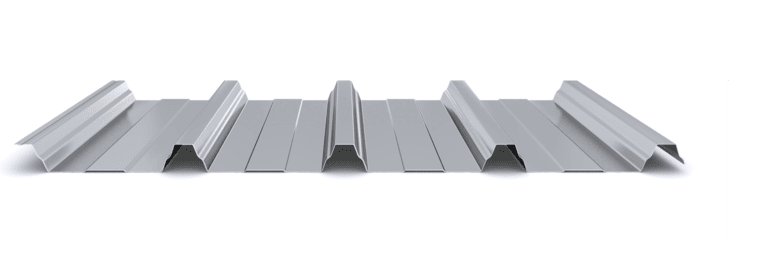
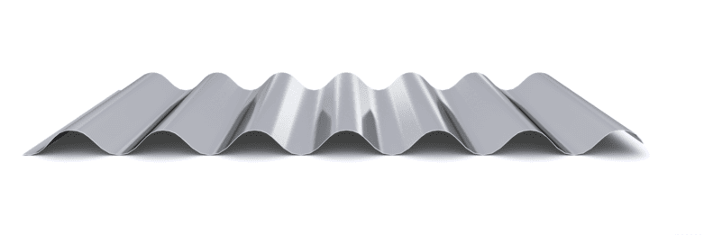
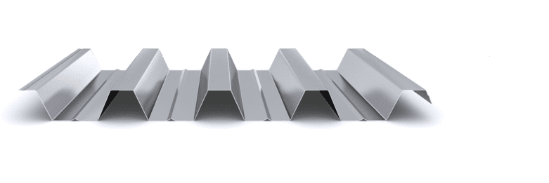
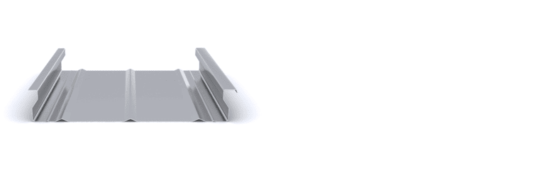
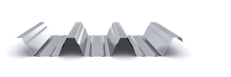
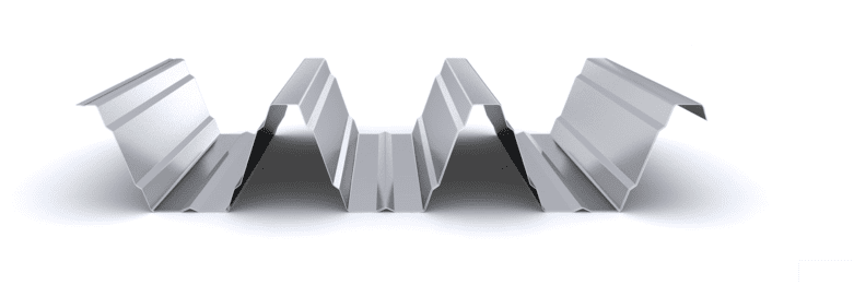
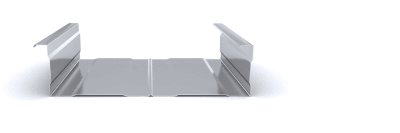
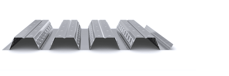
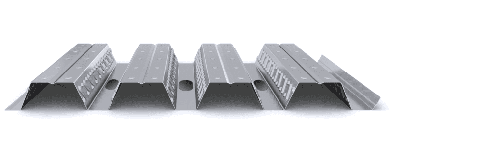
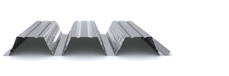
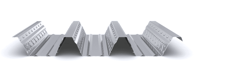
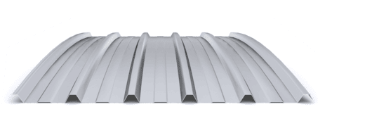
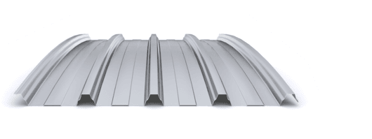
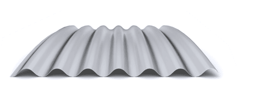
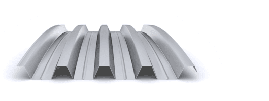
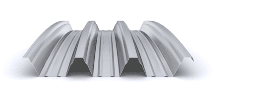
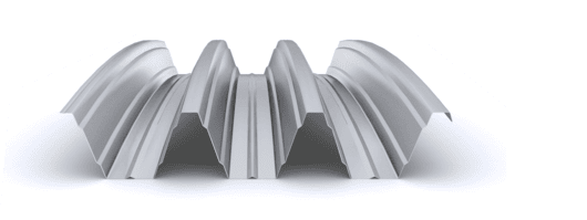
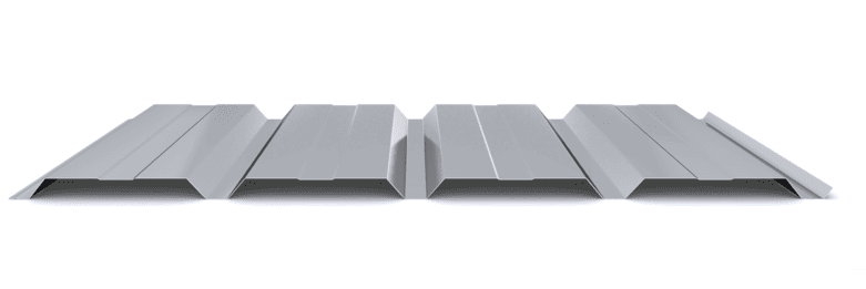
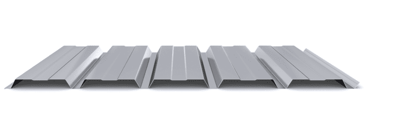
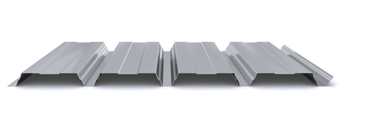
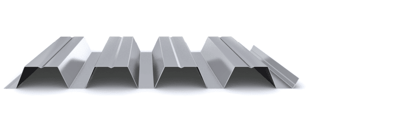
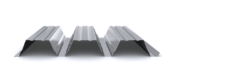
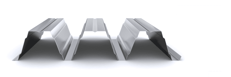
The lost formwork system consists of a galvanized steel ribbed profile that serves as formwork for a concrete slab executed in situ. The main function of the corrugated profile is to support the loads of execution and pouring of concrete, avoiding the need for shoring.

Unlike the composite slab solution, in the lost formwork solution the profiles do not have inlays and do not subsequently collaborate with the concrete slab. Due to this lack of contribution from the sheet metal, the use of positive reinforcement in the slab is mandatory, using a bar in each rib of the profile. Using this solution, light slabs can be made, with a self-weight of less than 2 kN/m², through an agile and simple execution procedure.

The main advantages of permanent formwork are:
  • Versatility: Adapts to any type of plant, offering flexibility in architectural design.
  • Strength/Weight Ratio: Provides greater resistance with a lower own weight, which allows reducing the overall weight of the structure.
  • Speed ​​of installation: The elimination of shoring allows the concreting of more than one floor simultaneously, considerably reducing the execution time.
  • Cost Reduction: A reduction in labor costs is achieved by avoiding shoring and in materials, by using a smaller volume of concrete. This implies a reduction in the weight of the structure and waste.

In addition to the main advantages, permanent formwork (non-composite) offers additional benefits, such as the simplicity of the construction process, ease of on-site stockpiling and cleaning, its function as formwork providing a safe platform to work on, and its contribution to structural bracing, thus improving its functionality and efficiency in construction.

Featured Products

  • Maximizes clearance between floors
  • Without shoring up to 4 m
  • Thickness: 0,75 – 1,2 mm
  • Slab depth from 110 mm
  • Up to 2.500 m² / transport
  • Light and strong
  • Without shoring up to 5 m
  • Thickness: 0,75 – 1,5 mm
  • Slab depth from 140 mm
  • Up to 2.500 m² / transport
  • Robustness and acoustic comfort
  • Without shoring up to 6 m
  • Thickness: 0,75 – 1,5 mm
  • Slab depth from 200 mm
  • Up to 2.100 m² / transport

Projects

Latest projects

Start designing yout project

Request calculation report

Complete the form below to receive a detailed report justifying the most suitable enclosure profile. You will receive the information as soon as possible.

Building characteristics
Industrial roof application loads
(1) For sections of the roof profile with 2, 3, 4 or more supports, indicate the greatest distances between supports that appear in your project.
Type of environment
Attached documentation
Additional comments
Contact information
Project data
Building characteristics
Application loads for the industrial facade
(1) For sections of the façade profile with 2, 3, 4 or more supports, indicate the greatest distances between supports that are presented in your project.
Type of environment
Attached documentation
Additional comments
Contact information
Project data
Building characteristics
Deck loads
(1) For sections of the roof profile with 2, 3, 4 or more supports, indicate the greatest distances between supports that appear in your project.
Type of environment
Attached documentation
Additional comments
Contact information
Project data
Structure features
Composite slab characteristics
(1) For the sections of the composite slab with 2, 3, 4 or more supports, indicate the greatest distances between supports that appear in your project. Span length < 5,00 m.
Type of environment
Attached documentation
Additional comments
Contact information
Project data
Building characteristics
Characteristics of the facade
Roof typology

(1) Indicate the length of the span of the arch, which is the greatest horizontal distance between the supports of the curved roofing.

(2) Plan-view dimension representing the full length of the curved roof measured perpendicular to the arch span.

(3) Specify the obstructed area under the canopy, in square meters, as a proportion of the total area of the front or side (transverse or longitudinal) façade, in order to calculate the obstruction factor. If it is a closed construction or there is no obstruction area, indicate 0 m².

Environment characteristics
Type of environment
Attached documentation
Additional comments
Contact information
Project data