Request a
calculation form

Home / Solutions / Self-supporting multilayer facade

Self-supporting multilayer facade

Croquis sistema forjado colaborante - esquema

The self-supporting multi-layer industrial facade is composed of several profiles, with the inner support profile fixed directly on the main structure, without the need for a secondary structure.

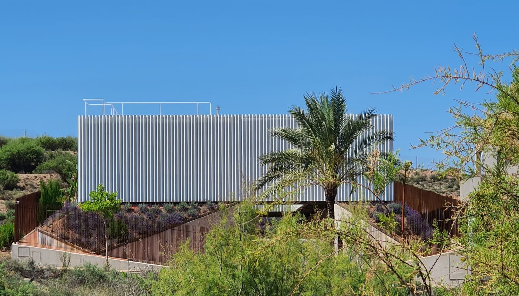
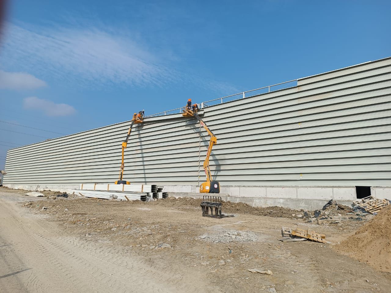
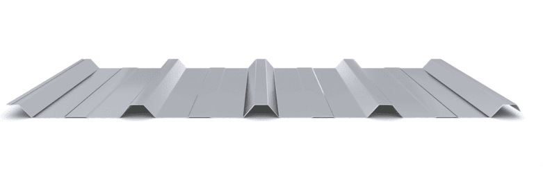
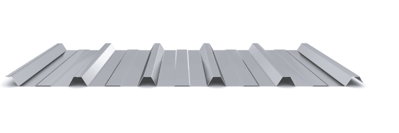
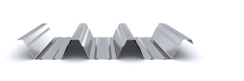
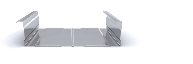
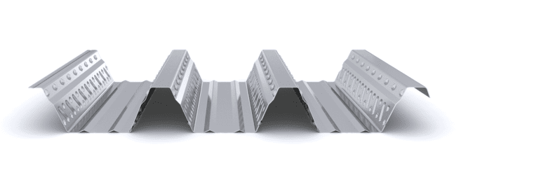
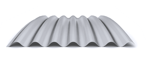
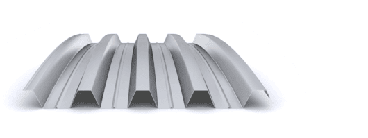
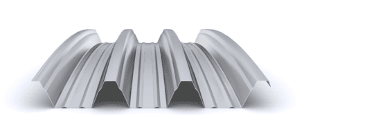
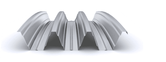
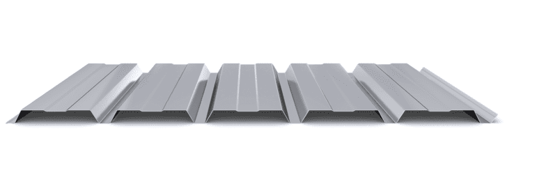
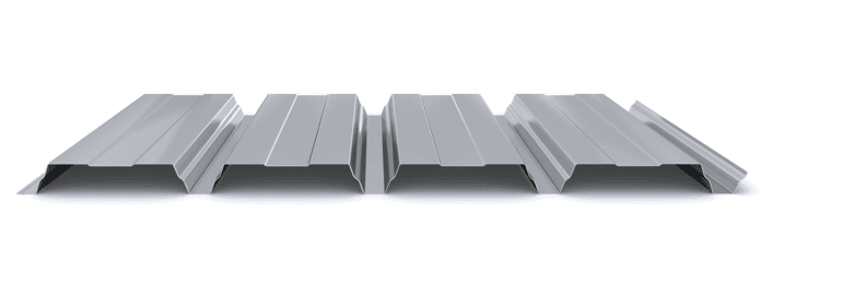
The self-supporting multi-layer industrial façade is made up of a ribbed exterior cladding profile, which acts as a sealing element, and an interior support tray profile that performs the resistant function. Both profiles are fixed to each other through the ribs of the tray profile, which maintain the space necessary to house the insulation. Its main function is to provide a watertight closure in constructions that require thermal conditioning of the interior.

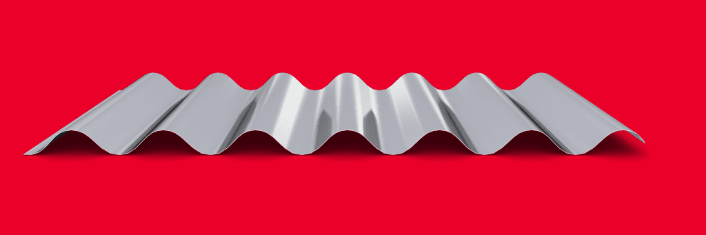
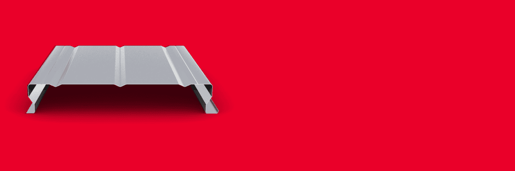
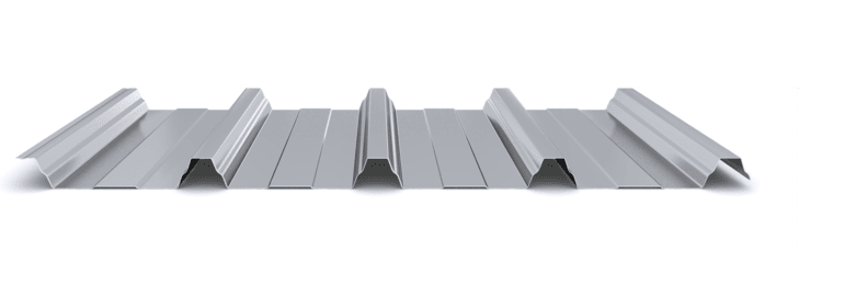
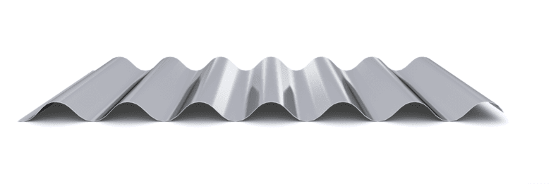
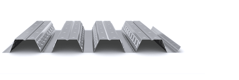
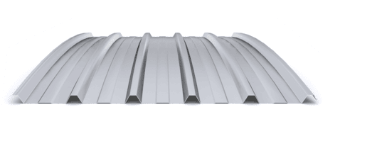
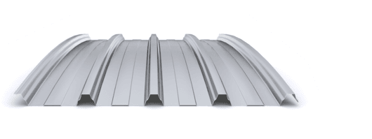
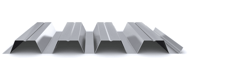
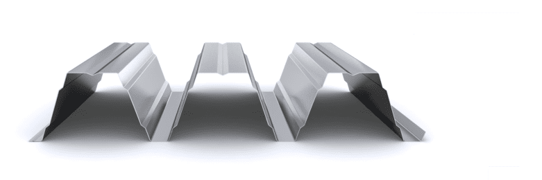
The corrugated profile of the exterior cladding will meet the mechanical requirements specified in the project and will also guarantee the watertightness of the façade. The interior support tray profile will mainly comply with the mechanical requirements specified in the project. This interior support profile will be installed on the main structural structure, which is generally composed of metal, concrete or wooden frames. The main advantage of this system is the elimination of the secondary structure or purlins, since the support profile can reach spans of up to 6 meters between supports with the INCO 157.1 Tray profile, and up to 10 meters with the INCO 155.3 Facade profile. By dispensing with the secondary structure, the installation performance of the facade is considerably improved.

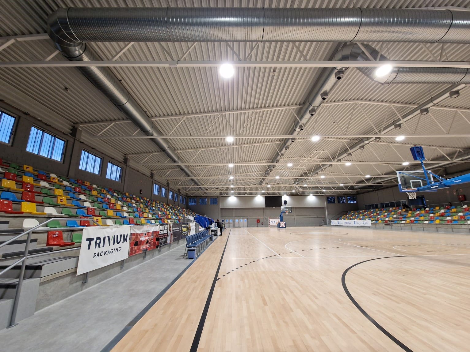
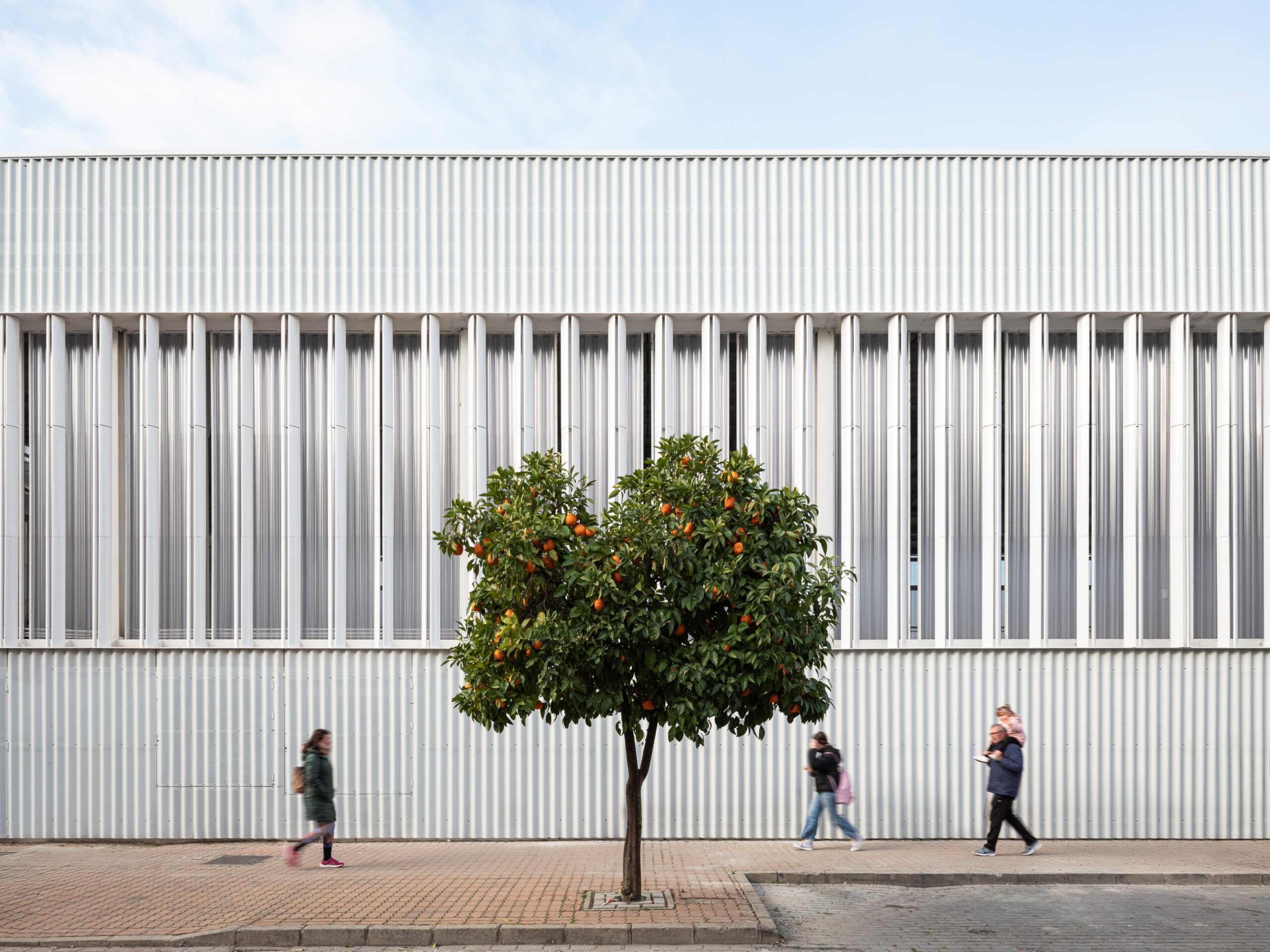
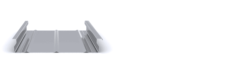
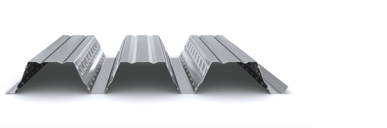
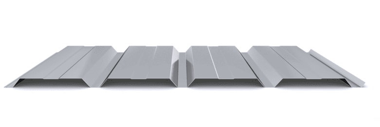
En aquellos recintos donde se requiera mejorar el confort acústico, se pueden emplear soluciones con el perfil bandeja de soporte interior microperforado, para incrementar la absorción acústica de la fachada. These perforations are made in the central part of the trays or in the profile webs in deep profiles. Typically, a R5T8 type perforation is used for the perforations in the central part of the trays and for the perforations in the webs of the deep profiles.

Featured Products

  • Symmetry and aesthetics
  • Self-supporting up to 4 m
  • Thickness: 0,6 – 1,0 mm
  • Up to 4.100 m² / transport
  • Smooth interior finishes
  • Self-supporting up to 5 m
  • Thickness: 0,6 – 1,0 mm
  • Up to 900 m² / transport
  • Smooth interior finishes
  • Self-supporting up to 6 m
  • Thickness: 0,7 – 1,5 mm
  • Up to 500 m² / transport

Projects

Latest projects

Start designing yout project

Request calculation report

Complete the form below to receive a detailed report justifying the most suitable enclosure profile. You will receive the information as soon as possible.

Building characteristics
Industrial roof application loads
(1) For sections of the roof profile with 2, 3, 4 or more supports, indicate the greatest distances between supports that appear in your project.
Type of environment
Attached documentation
Additional comments
Contact information
Project data
Building characteristics
Application loads for the industrial facade
(1) For sections of the façade profile with 2, 3, 4 or more supports, indicate the greatest distances between supports that are presented in your project.
Type of environment
Attached documentation
Additional comments
Contact information
Project data
Building characteristics
Deck loads
(1) For sections of the roof profile with 2, 3, 4 or more supports, indicate the greatest distances between supports that appear in your project.
Type of environment
Attached documentation
Additional comments
Contact information
Project data
Structure features
Composite slab characteristics
(1) For the sections of the composite slab with 2, 3, 4 or more supports, indicate the greatest distances between supports that appear in your project. Span length < 5,00 m.
Type of environment
Attached documentation
Additional comments
Contact information
Project data
Building characteristics
Characteristics of the facade
Roof typology

(1) Indicate the length of the span of the arch, which is the greatest horizontal distance between the supports of the curved roofing.

(2) Plan-view dimension representing the full length of the curved roof measured perpendicular to the arch span.

(3) Specify the obstructed area under the canopy, in square meters, as a proportion of the total area of the front or side (transverse or longitudinal) façade, in order to calculate the obstruction factor. If it is a closed construction or there is no obstruction area, indicate 0 m².

Environment characteristics
Type of environment
Attached documentation
Additional comments
Contact information
Project data