Request a
calculation form

Home / Solutions / Multilayer curved roof

Multilayer curved roof

croquis de sistema cubierta industrial multicapa- esquema

The multi-layer curved roof is formed by several non-self-supporting curved profiles fixed on the secondary structure.

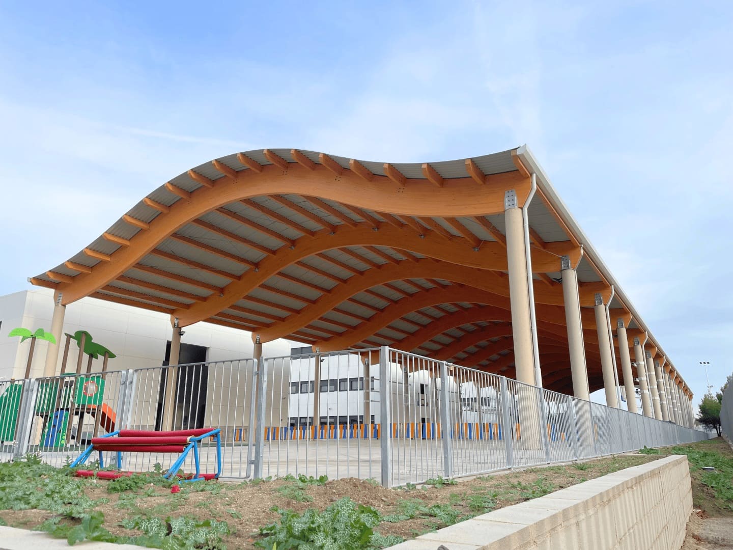
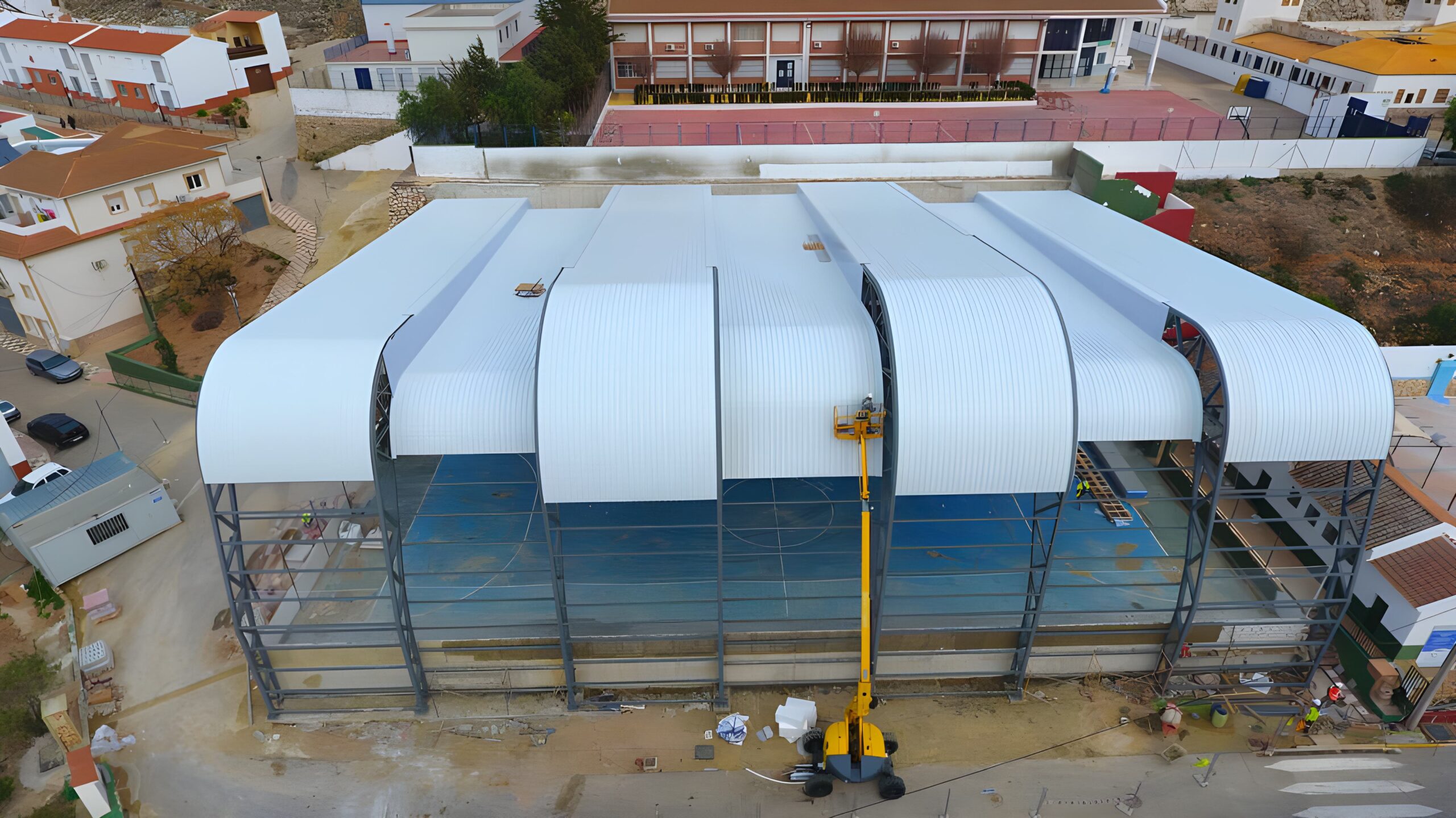
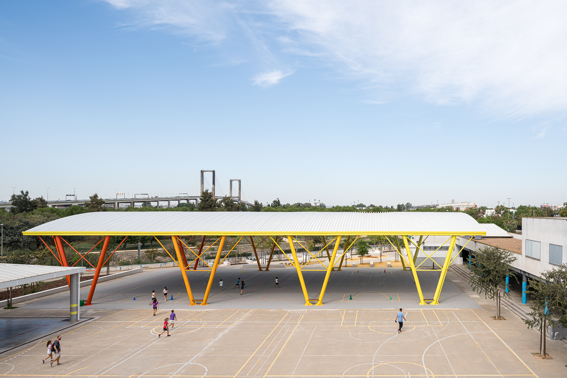
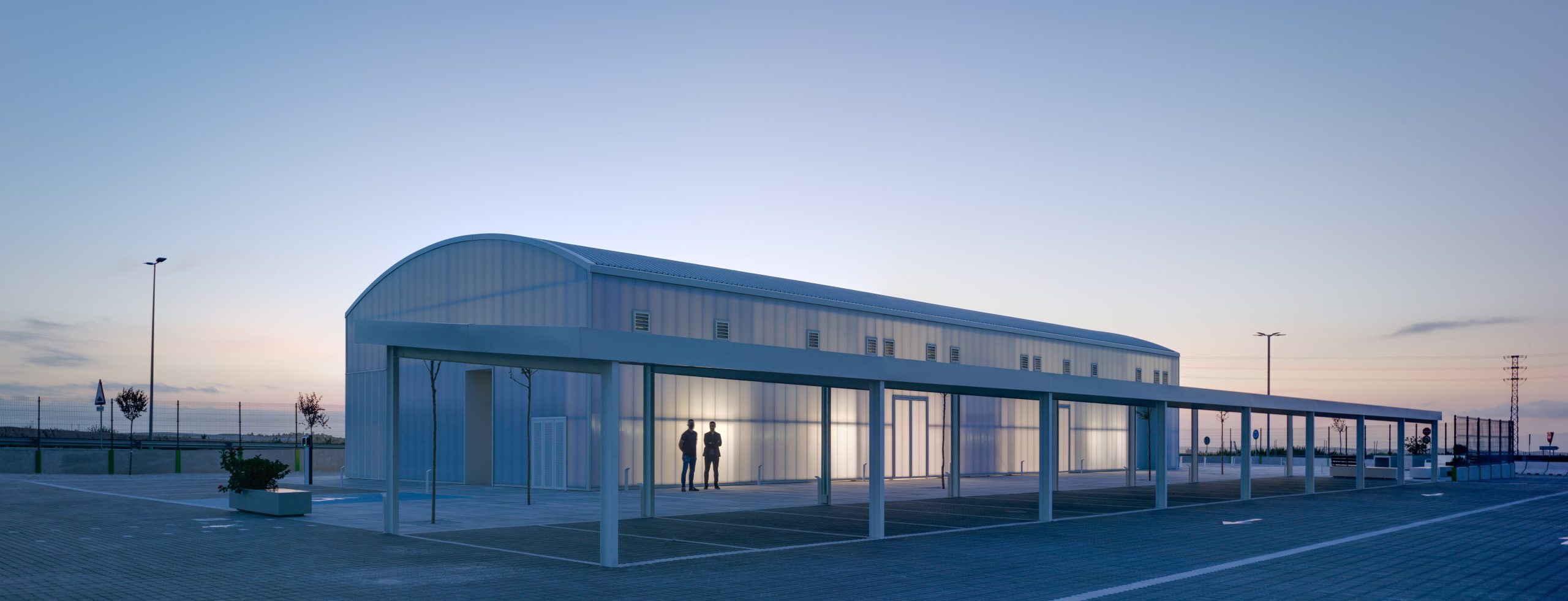
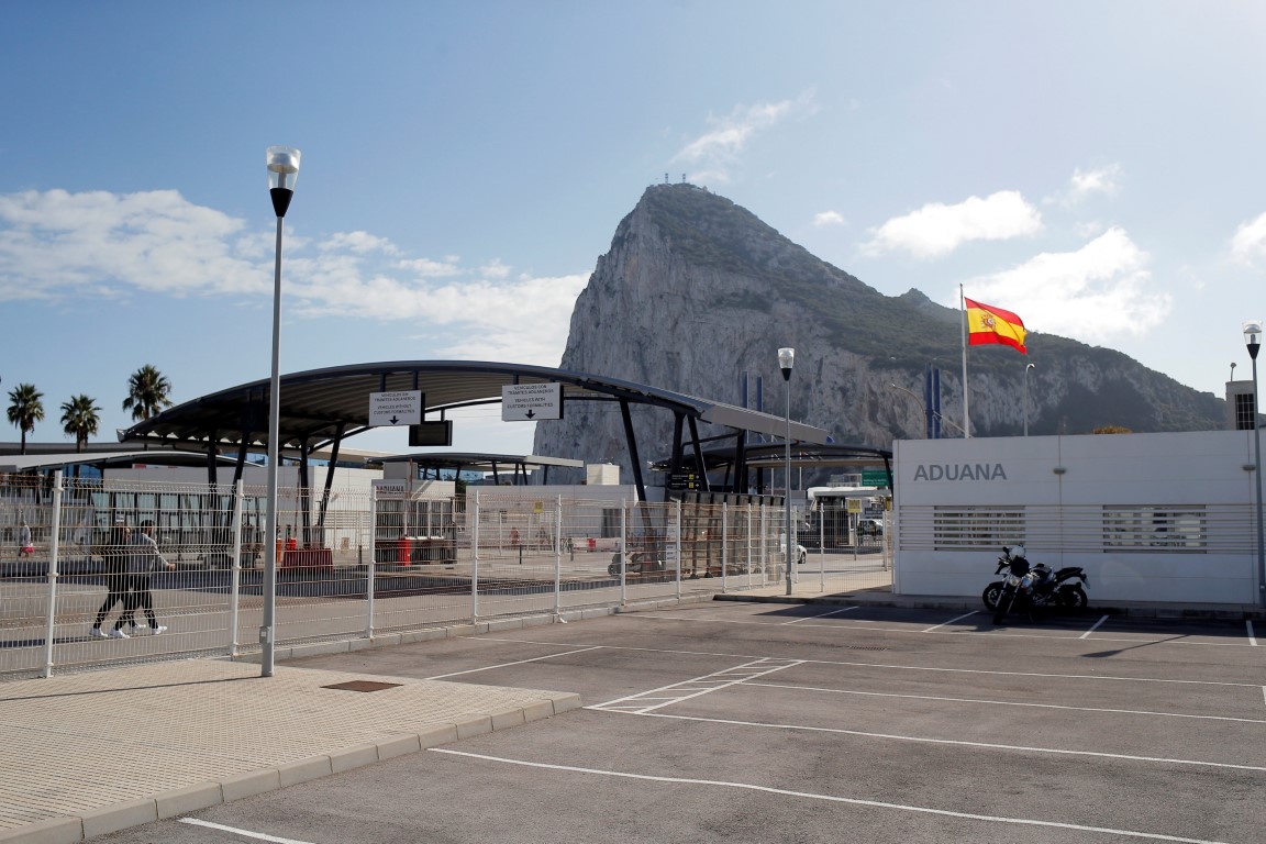
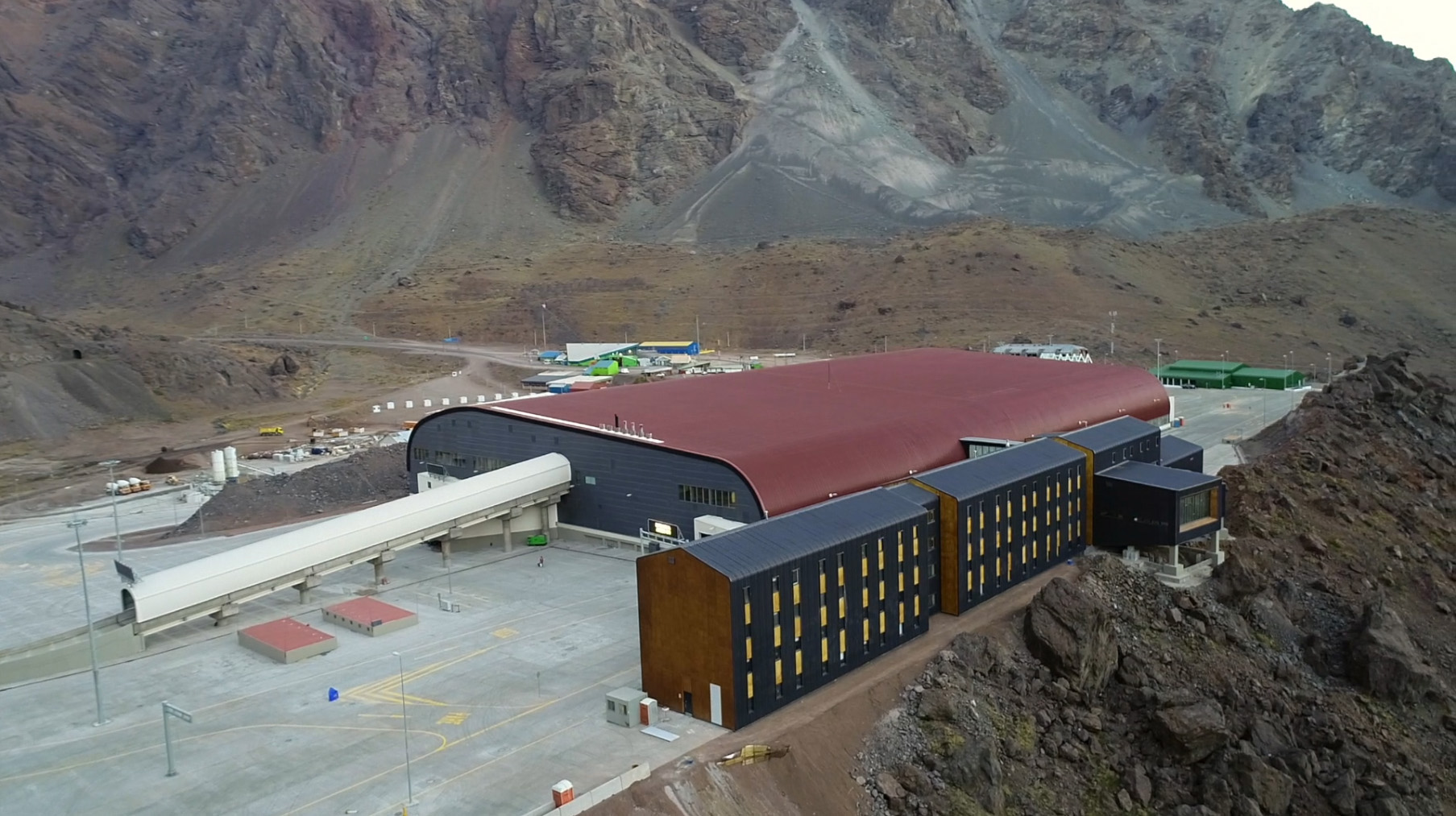
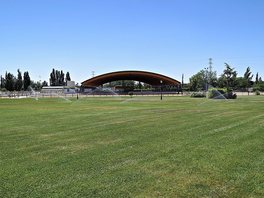
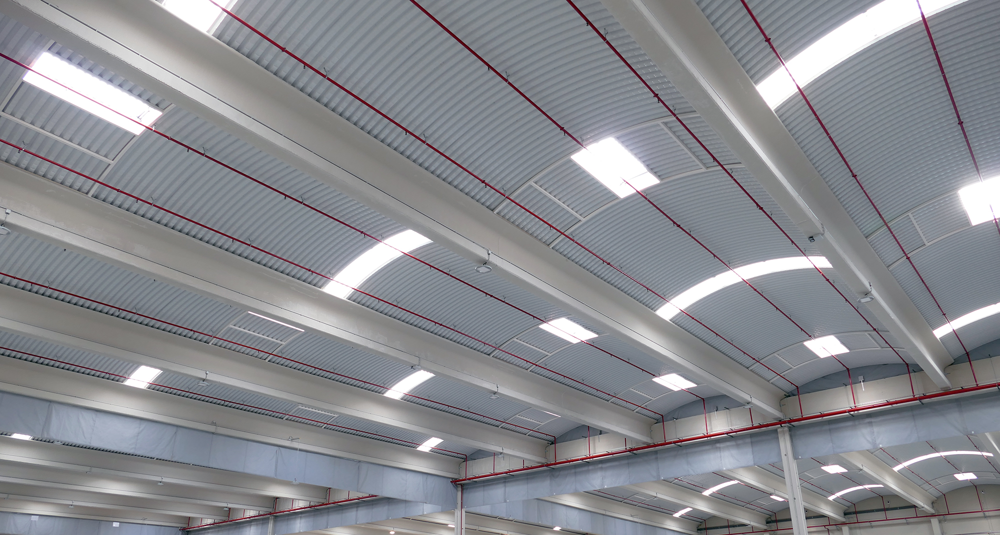
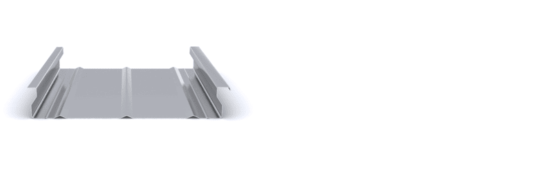
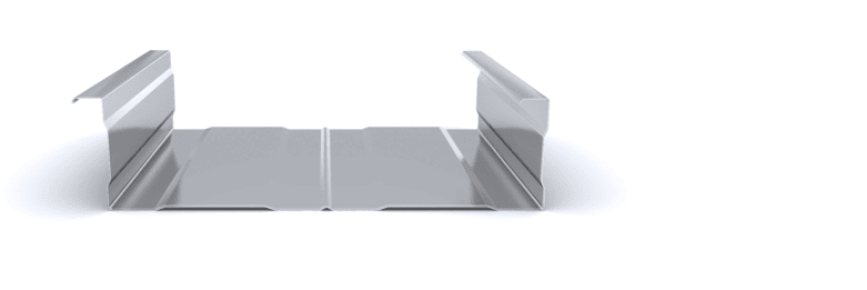
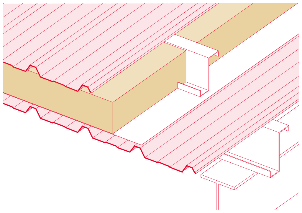
The multi-layer curved cover is formed by an external non-self-supporting curved profile, which acts as a sealing element, and by an internal support non-self-supporting curved profile that performs the resistant function. Both profiles are fixed to each other using a separator profile, which maintains the necessary distance to accommodate the insulation. The main function of this solution is to provide a watertight seal on the curved roofs of buildings that require thermal conditioning inside.

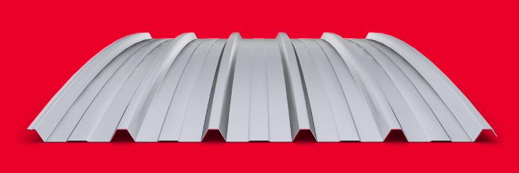
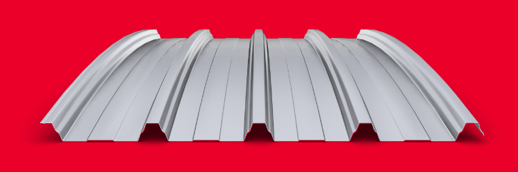
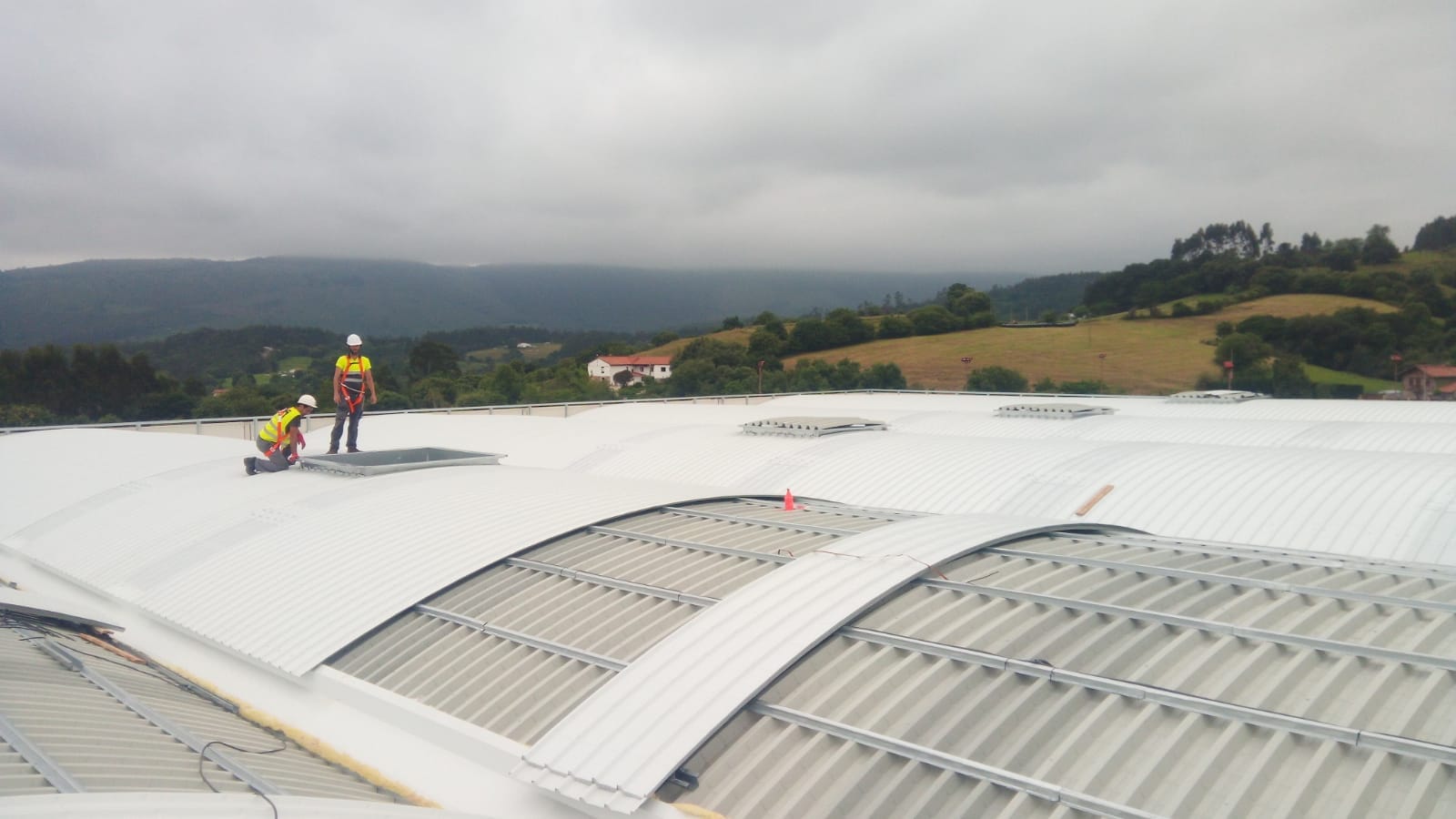
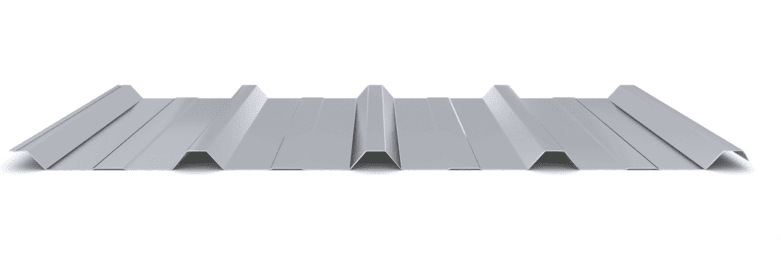
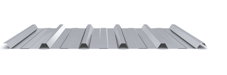
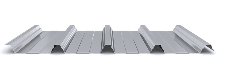
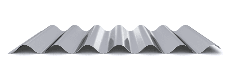
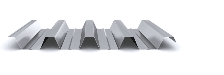
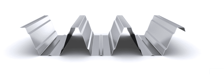
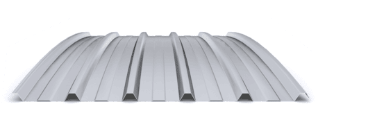
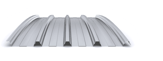
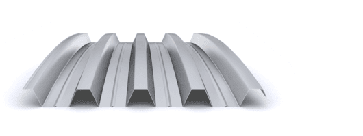
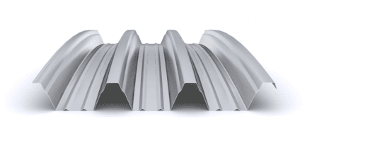
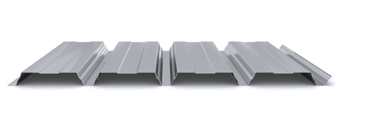
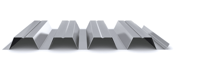
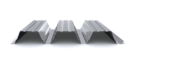
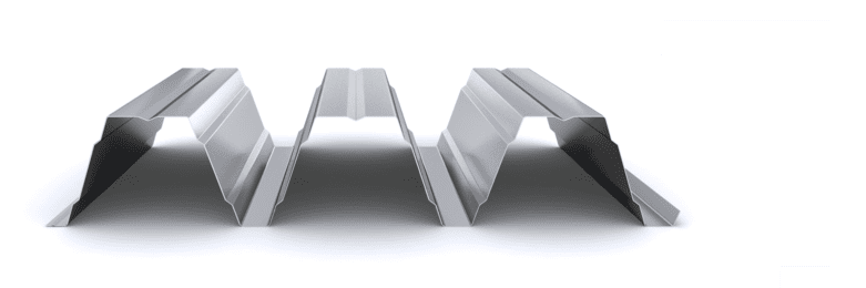
The curved profile of the exterior cladding will meet the mechanical requirements specified in the project and will also guarantee the watertightness of the roof. The curved interior support profile will meet the mechanical requirements specified in the project. This interior support profile will be installed on a secondary structure, generally composed of metal, concrete or wooden straps, separated between 1.50 and 3 meters. The profiles are more suitable for this curved roofing solution: INCO 30.5 Curved, INCO 44.4 Curvedand INCO 70.4 Curved profiles.

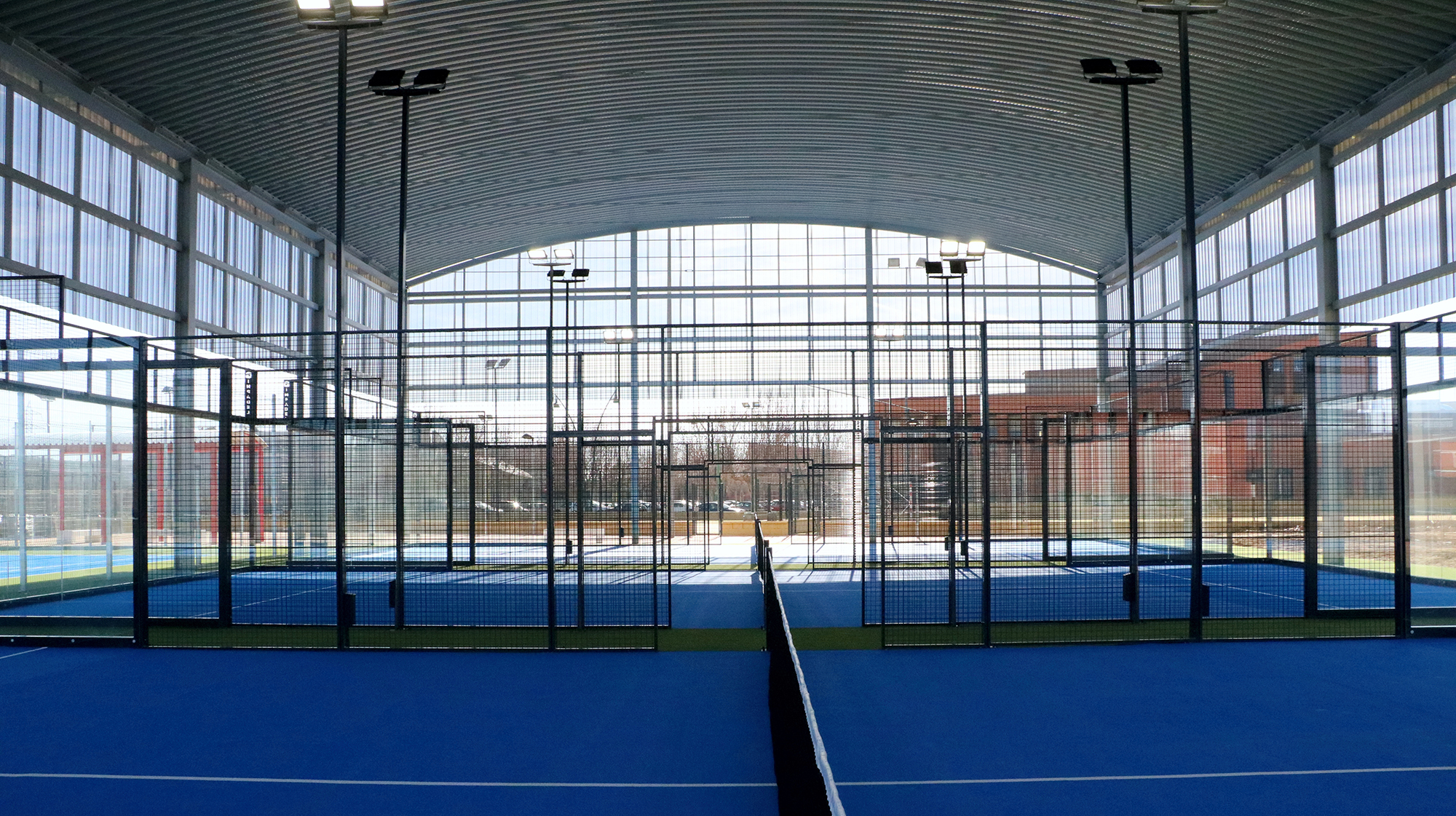
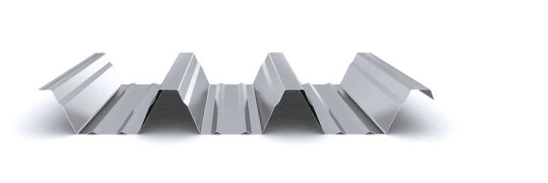
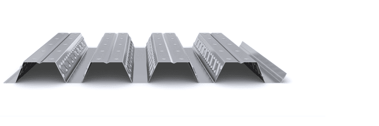
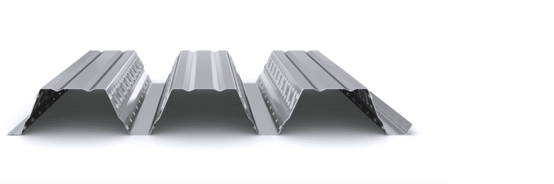
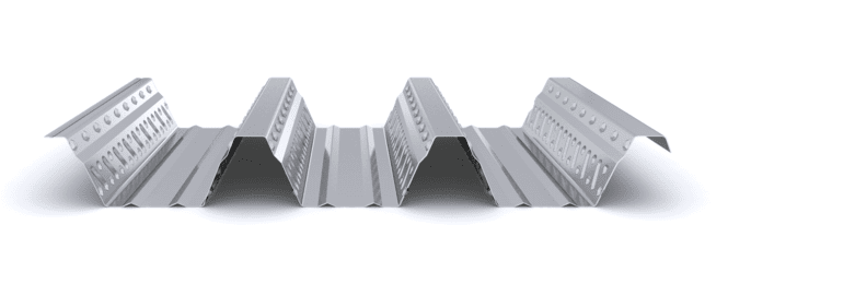
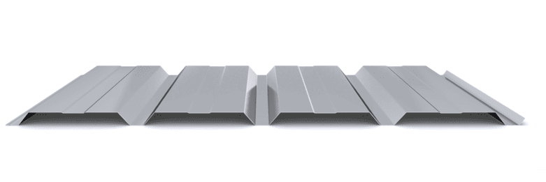
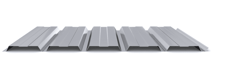
In those rooms where it is required to improve acoustic comfort, solutions with the curved micro-perforated interior support profile can be used to increase the acoustic absorption of the cover. These perforations can be made in the webs of the profile in profiles with a large depth, or throughout its surface in profiles with a reduced depth. Typically, drilling of type R5T8 is used for perforations in the webs and type R3T6 for perforations throughout the surface.

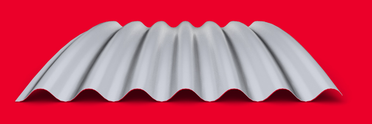
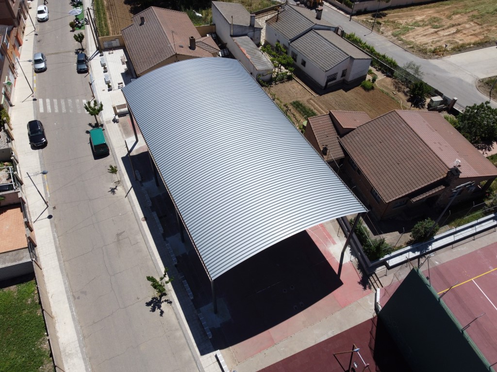
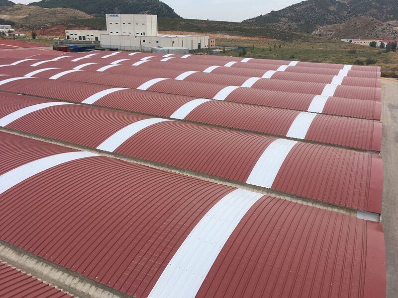
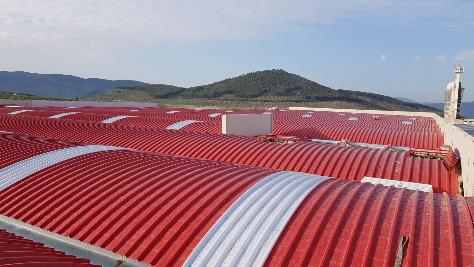
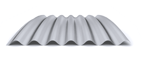
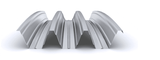
The curvatura of the trapezoidal profile is recorded through a series of equidistant contours which, with a few folds, provide the necessary curvatura.

Featured Products

  • Economy and resistance
  • Support separation up to 3.00 m
  • Thicknesses: 0.60 – 1.20 mm
  • Up to 3,900 m² / transport
  • Good resistance
  • Support separation up to 3.50 m
  • Thicknesses: 0.60 – 1.20 mm
  • Up to 3,600 m² / transport
  • Symmetry and aesthetics
  • Support separation up to 4.00 m
  • Thicknesses: 0.60 – 1.00 mm
  • Up to 4,100 m² / transport

Projects

Latest projects

Start designing yout project

Request calculation report

Complete the form below to receive a detailed report justifying the most suitable enclosure profile. You will receive the information as soon as possible.

Building characteristics
Industrial roof application loads
(1) For sections of the roof profile with 2, 3, 4 or more supports, indicate the greatest distances between supports that appear in your project.
Type of environment
Attached documentation
Additional comments
Contact information
Project data
Building characteristics
Application loads for the industrial facade
(1) For sections of the façade profile with 2, 3, 4 or more supports, indicate the greatest distances between supports that are presented in your project.
Type of environment
Attached documentation
Additional comments
Contact information
Project data
Building characteristics
Deck loads
(1) For sections of the roof profile with 2, 3, 4 or more supports, indicate the greatest distances between supports that appear in your project.
Type of environment
Attached documentation
Additional comments
Contact information
Project data
Structure features
Composite slab characteristics
(1) For the sections of the composite slab with 2, 3, 4 or more supports, indicate the greatest distances between supports that appear in your project. Span length < 5,00 m.
Type of environment
Attached documentation
Additional comments
Contact information
Project data
Building characteristics
Characteristics of the facade
Roof typology

(1) Indicate the length of the span of the arch, which is the greatest horizontal distance between the supports of the curved roofing.

(2) Plan-view dimension representing the full length of the curved roof measured perpendicular to the arch span.

(3) Specify the obstructed area under the canopy, in square meters, as a proportion of the total area of the front or side (transverse or longitudinal) façade, in order to calculate the obstruction factor. If it is a closed construction or there is no obstruction area, indicate 0 m².

Environment characteristics
Type of environment
Attached documentation
Additional comments
Contact information
Project data