

Request a
calculation form

25.Composite floor REI 180: depth optimisation

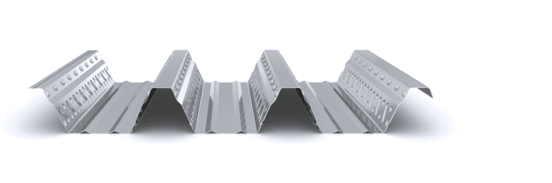
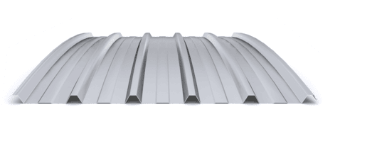
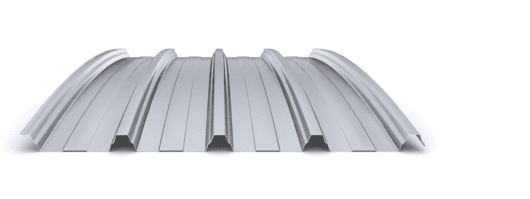
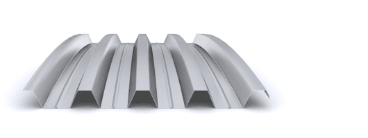
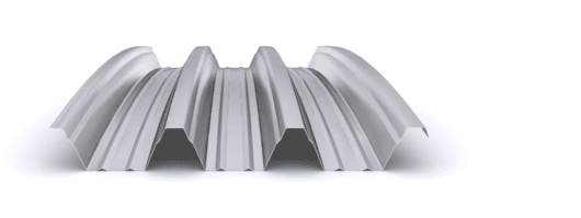
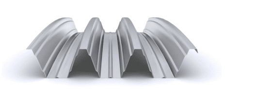
Comparative calculation example for an REI 180 composite floor using three INCO profiles under the same conditions. The INCO 100.3 R Composite Deck configuration reduces the total floor depth to 190 mm and allows construction without props, compared with 200 mm for INCO 70.4 and 220 mm for INCO 100.3.

The purpose of this example is to assess how the choice of composite deck profile affects the minimum floor slab depth, reinforcement and need for propping when the required fire resistance reaches REI 180. To isolate the effect of the profile, three solutions with identical geometry, loads and structural systems are compared.

Initial assumptions

The following conditions are used:

Geometry and structural system

  • Spans in the composite stage: 4 equal spans
  • Span length: 3.80 m (V1 = V2 = V3 = V4)
  • Deck layout in the formwork stage: 2 sheets (2+2 spans)
  • Comparison criterion: possibility of construction without propping
  • Required fire resistance: REI 180
  • Levelling layer or floor finish included for thermal insulation purposes: 0 mm (conservative assumption)

Technical note: To improve compliance with the thermal insulation criterion for requirements above REI 30, up to 20 mm of a potential concrete levelling layer or floor finish with equivalent thermal properties may be taken into account. This example assumes 0 mm, providing a conservative assessment of thermal insulation.

  • Steel supports: 100 mm wide

Materials

  • Base steel: S320GD (resistance tables available for S280GD steel)
  • Structural concrete: HA-25

Actions

  • Additional permanent loads: 2.0 kN/m²
  • Imposed load: 5.0 kN/m²
  • Floor self-weight: accounted for internally by the calculation software

Verification criteria

  • Formwork stage: L/180 and an absolute limit of 20 mm, including the ponding effect
  • Composite stage: L/700 + 5 mm (spans > 3.50 m)
  • Verification in accordance with Eurocodes 3 and 4; fire resistance verification in accordance with UNE-EN 1994-1-2

Comparative results

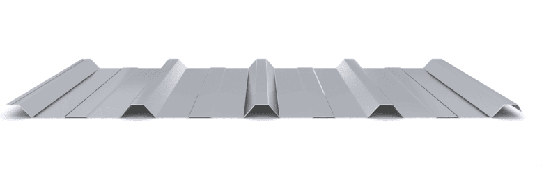
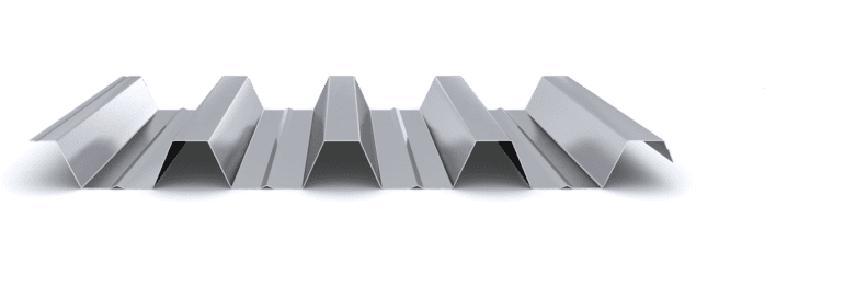
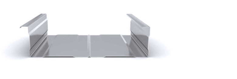
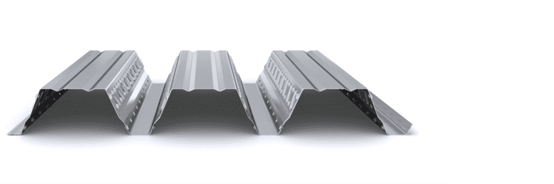
Configuration A — INCO 100.3 R Composite

  • Total floor depth (H): 190 mm
  • Top mesh reinforcement: 150×150×8
  • Fire reinforcement: Ø6 mm per trough
  • Props during the formwork stage: not required

Note:
The minimum depth is governed by the thermal insulation verification and the required concrete cover. The solution satisfies ULS, SLS and REI 180 simultaneously, without intermediate propping.

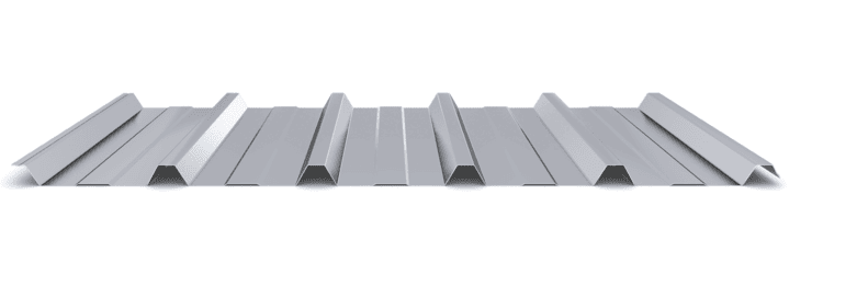
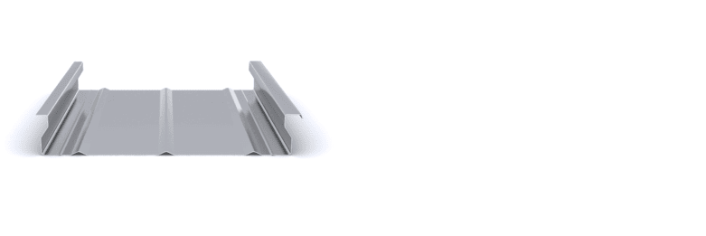
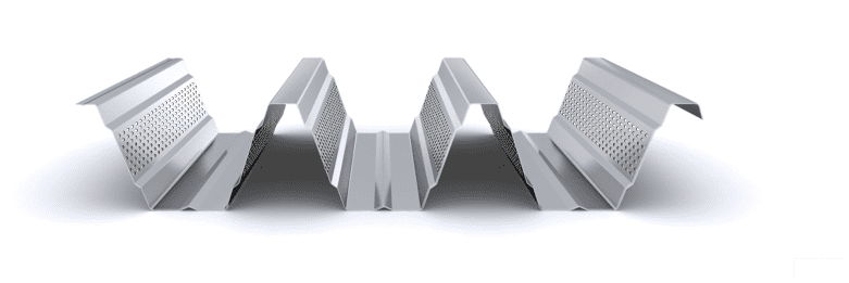
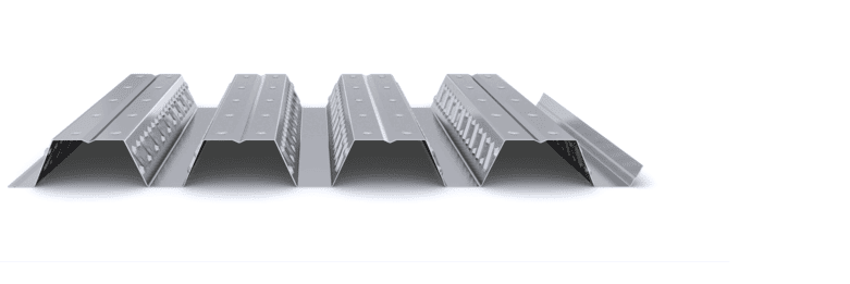
Configuration B — INCO 70.4 Composite

  • Total floor depth (H): 200 mm
  • Top mesh reinforcement: 200×200×10
  • Fire reinforcement: Ø8 mm per trough
  • Props during the formwork stage: one line per span

Note:
To meet REI 180, this profile requires a greater depth and more reinforcement than the INCO 100.3 R solution. It also requires one line of props per span under the conditions analysed.

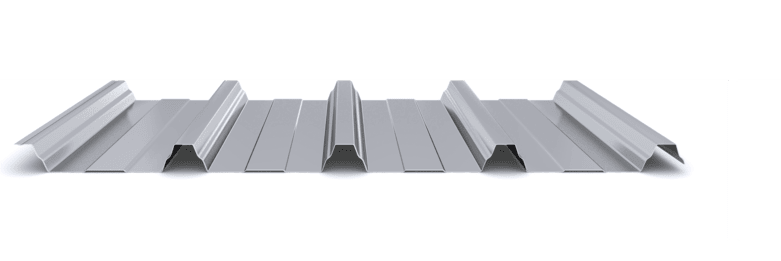
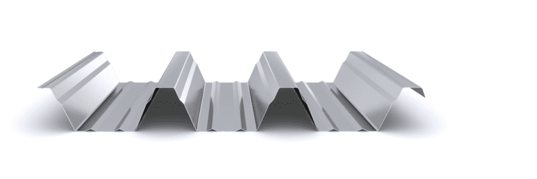
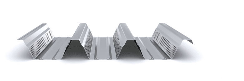
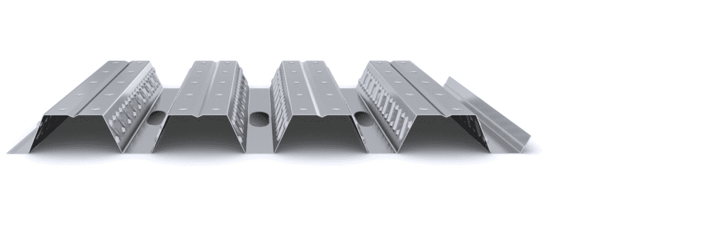
Configuration C — INCO 100.3 Composite

  • Total floor depth (H): 220 mm
  • Top mesh reinforcement: 150×150×8
  • Fire reinforcement: Ø8 mm per trough
  • Props during the formwork stage: not required

Note:
This solution meets the requirements without props, but requires greater structural depth than the optimised INCO 100.3 R Composite.

Example outcome

The INCO 100.3 R Composite configuration achieves a total floor depth of 190 mm without props, reducing the depth by 10 mm compared with the INCO 70.4 and by 30 mm compared with the INCO 100.3. It also avoids the propping required by the INCO 70.4.

Structural interpretation

Under the assumptions analysed, the REI 180 requirement governs the minimum floor depth through the thermal insulation criterion. For this load range, this verification is more restrictive than the resistance of the slab in the composite stage.

Fire resistance therefore governs the minimum floor depth. For this load range, the thermal insulation verification is more restrictive than the resistance of the slab in the composite stage.

The INCO 100.3 R Composite Deck allows the total floor depth to be reduced compared with the other profiles in the range.

The INCO 70.4 Composite Deck requires greater depth than the INCO 100.3 R and one line of props per span.

The INCO 100.3 Composite Deck meets the requirements without props, but at the cost of greater depth.

The difference is not marginal:

  • Depth reduction compared with the INCO 100.3 Composite Deck: ≈ 30 mm
  • Depth reduction compared with the INCO 70.4 Composite Deck: ≈ 10 mm
  • Props eliminated compared with the INCO 70.4 Composite Deck

In multi-storey buildings, reducing the floor depth may lower the cumulative structural thickness or provide more clear headroom. The effect on self-weight and concrete volume must be assessed for each profile, as it also depends on the geometry of the ribs.

Conclusion

For an REI 180 composite floor, the choice of profile can be decisive in optimising structural depth, reinforcement and construction requirements. Under the assumptions analysed:

  • The INCO 100.3 R Composite achieves H = 190 mm while allowing construction without props.
  • The INCO 70.4 Composite requires H = 200 mm, more reinforcement than the INCO 100.3 R and one line of props per span.
  • The INCO 100.3 Composite allows construction without props but requires H = 220 mm.

This example shows that, when fire resistance requirements are high, profile selection is a structural and construction optimisation variable, not merely a geometric choice.

Composite floor calculation report

The example above is for guidance only and is based on specific assumptions regarding load, span, fire resistance and structural system.

The final design of a composite floor must be documented in a project-specific calculation report, including verification of:

  • Ultimate limit states (bending and shear).
  • Serviceability limit states in the formwork and composite stages.
  • Fire resistance in accordance with UNE-EN 1994-1-2.
  • Construction requirements and the adopted structural system.

Incoperfil’s Technical Department issues design reports tailored to the actual conditions of each project, in accordance with Eurocodes 3 and 4. A report can be requested using the technical form available on the website, providing the spans, loads and fire resistance requirements.

Request the composite floor calculation report using the following link:

Composite floor calculation report

Related articles

For a full description of the system, design criteria, design principles, resistance tables, construction details and installation procedures, consult the Incoperfil Technical Manual for Composite Floors, available after registration in the “Documentation” section of the website.

Last updated: October 2026

© Incoperfil. All rights reserved.
The technical content of this article forms part of the Incoperfil Technical Manual for Composite Floors and the documentation registered by Incoperfil with ColorIURIS (Record No. 1-INCOPERFIL-12.2025).

Home / 25.Composite floor REI 180: depth optimisation

Guía técnica

24987

25.Composite floor REI 180: depth optimisation

Comparative calculation example for an REI 180 composite floor using three INCO profiles under the same conditions. The INCO 100.3 R Composite Deck configuration reduces the total floor depth to 190 mm and allows construction without props, compared with 200 mm for INCO 70.4 and 220 mm for INCO 100.3.

The purpose of this example is to assess how the choice of composite deck profile affects the minimum floor slab depth, reinforcement and need for propping when the required fire resistance reaches REI 180. To isolate the effect of the profile, three solutions with identical geometry, loads and structural systems are compared.

Initial assumptions

The following conditions are used:

Geometry and structural system

  • Spans in the composite stage: 4 equal spans
  • Span length: 3.80 m (V1 = V2 = V3 = V4)
  • Deck layout in the formwork stage: 2 sheets (2+2 spans)
  • Comparison criterion: possibility of construction without propping
  • Required fire resistance: REI 180
  • Levelling layer or floor finish included for thermal insulation purposes: 0 mm (conservative assumption)

Technical note: To improve compliance with the thermal insulation criterion for requirements above REI 30, up to 20 mm of a potential concrete levelling layer or floor finish with equivalent thermal properties may be taken into account. This example assumes 0 mm, providing a conservative assessment of thermal insulation.
  • Steel supports: 100 mm wide

Materials

  • Base steel: S320GD (resistance tables available for S280GD steel)
  • Structural concrete: HA-25

Actions

  • Additional permanent loads: 2.0 kN/m²
  • Imposed load: 5.0 kN/m²
  • Floor self-weight: accounted for internally by the calculation software

Verification criteria

  • Formwork stage: L/180 and an absolute limit of 20 mm, including the ponding effect
  • Composite stage: L/700 + 5 mm (spans > 3.50 m)
  • Verification in accordance with Eurocodes 3 and 4; fire resistance verification in accordance with UNE-EN 1994-1-2

Comparative results

Configuration A — INCO 100.3 R Composite

  • Total floor depth (H): 190 mm
  • Top mesh reinforcement: 150×150×8
  • Fire reinforcement: Ø6 mm per trough
  • Props during the formwork stage: not required

Note: The minimum depth is governed by the thermal insulation verification and the required concrete cover. The solution satisfies ULS, SLS and REI 180 simultaneously, without intermediate propping.

Configuration B — INCO 70.4 Composite

  • Total floor depth (H): 200 mm
  • Top mesh reinforcement: 200×200×10
  • Fire reinforcement: Ø8 mm per trough
  • Props during the formwork stage: one line per span

Note: To meet REI 180, this profile requires a greater depth and more reinforcement than the INCO 100.3 R solution. It also requires one line of props per span under the conditions analysed.

Configuration C — INCO 100.3 Composite

  • Total floor depth (H): 220 mm
  • Top mesh reinforcement: 150×150×8
  • Fire reinforcement: Ø8 mm per trough
  • Props during the formwork stage: not required

Note: This solution meets the requirements without props, but requires greater structural depth than the optimised INCO 100.3 R Composite.

Example outcome

The INCO 100.3 R Composite configuration achieves a total floor depth of 190 mm without props, reducing the depth by 10 mm compared with the INCO 70.4 and by 30 mm compared with the INCO 100.3. It also avoids the propping required by the INCO 70.4.

Structural interpretation

Under the assumptions analysed, the REI 180 requirement governs the minimum floor depth through the thermal insulation criterion. For this load range, this verification is more restrictive than the resistance of the slab in the composite stage.Fire resistance therefore governs the minimum floor depth. For this load range, the thermal insulation verification is more restrictive than the resistance of the slab in the composite stage.The INCO 100.3 R Composite Deck allows the total floor depth to be reduced compared with the other profiles in the range.The INCO 70.4 Composite Deck requires greater depth than the INCO 100.3 R and one line of props per span.The INCO 100.3 Composite Deck meets the requirements without props, but at the cost of greater depth.The difference is not marginal:

  • Depth reduction compared with the INCO 100.3 Composite Deck: ≈ 30 mm
  • Depth reduction compared with the INCO 70.4 Composite Deck: ≈ 10 mm
  • Props eliminated compared with the INCO 70.4 Composite Deck

In multi-storey buildings, reducing the floor depth may lower the cumulative structural thickness or provide more clear headroom. The effect on self-weight and concrete volume must be assessed for each profile, as it also depends on the geometry of the ribs.

Conclusion

For an REI 180 composite floor, the choice of profile can be decisive in optimising structural depth, reinforcement and construction requirements. Under the assumptions analysed:

  • The INCO 100.3 R Composite achieves H = 190 mm while allowing construction without props.
  • The INCO 70.4 Composite requires H = 200 mm, more reinforcement than the INCO 100.3 R and one line of props per span.
  • The INCO 100.3 Composite allows construction without props but requires H = 220 mm.

This example shows that, when fire resistance requirements are high, profile selection is a structural and construction optimisation variable, not merely a geometric choice.

Composite floor calculation report

The example above is for guidance only and is based on specific assumptions regarding load, span, fire resistance and structural system.The final design of a composite floor must be documented in a project-specific calculation report, including verification of:

  • Ultimate limit states (bending and shear).
  • Serviceability limit states in the formwork and composite stages.
  • Fire resistance in accordance with UNE-EN 1994-1-2.
  • Construction requirements and the adopted structural system.

Incoperfil’s Technical Department issues design reports tailored to the actual conditions of each project, in accordance with Eurocodes 3 and 4. A report can be requested using the technical form available on the website, providing the spans, loads and fire resistance requirements.Request the composite floor calculation report using the following link:Composite floor calculation report

Related articles


For a full description of the system, design criteria, design principles, resistance tables, construction details and installation procedures, consult the Incoperfil Technical Manual for Composite Floors, available after registration in the “Documentation” section of the website.
Last updated: October 2026© Incoperfil. All rights reserved.
The technical content of this article forms part of the Incoperfil Technical Manual for Composite Floors and the documentation registered by Incoperfil with ColorIURIS (Record No. 1-INCOPERFIL-12.2025).