






Request a
calculation form

23. Long Spans Without Propping with INCO 100.3

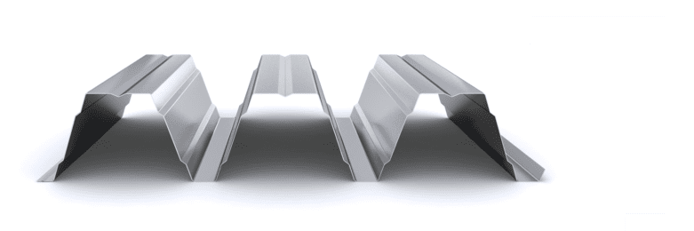
Technical design example using INCO 100.3 Composite Deck and REI 90 for long spans without propping. The analysis compares two sheet layouts during the formwork stage and shows how continuity makes it possible to increase the maximum achievable span from 4.10 m to 4.60 m.

Calculation example of an unpropped composite floor

The purpose of this example is to analyse the influence of the structural arrangement of the sheet during the formwork stage. Two layouts — 1+1+1+1 and 2+2 — are compared, keeping the 1.20 mm INCO 100.3 Composite Deck, loads, floor depth and REI 90 requirement constant. This makes it possible to directly assess the effect of sheet continuity on the achievable span without propping.

Starting assumptions

The following initial conditions are considered:

Geometry and arrangement

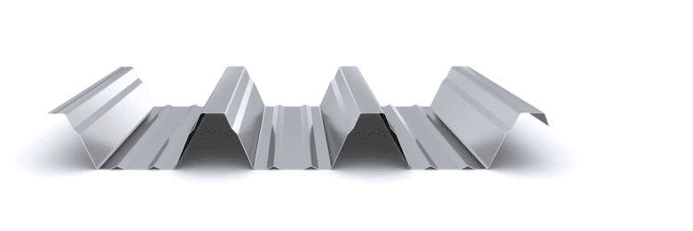
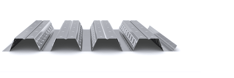
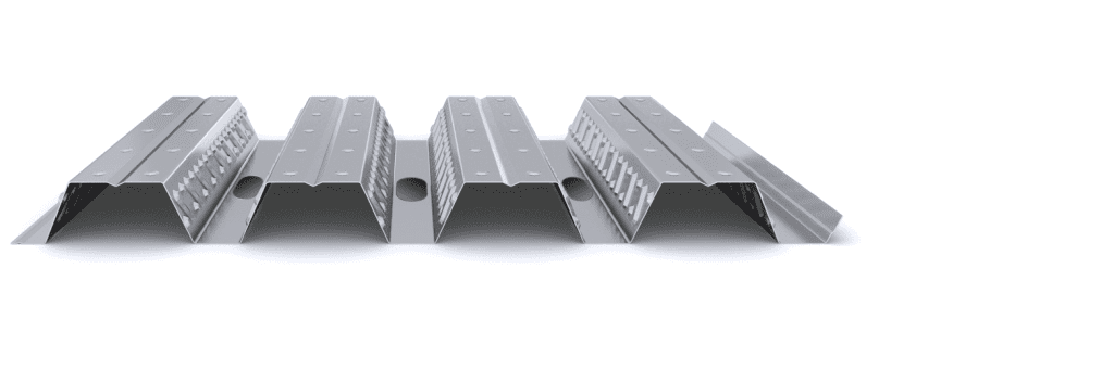
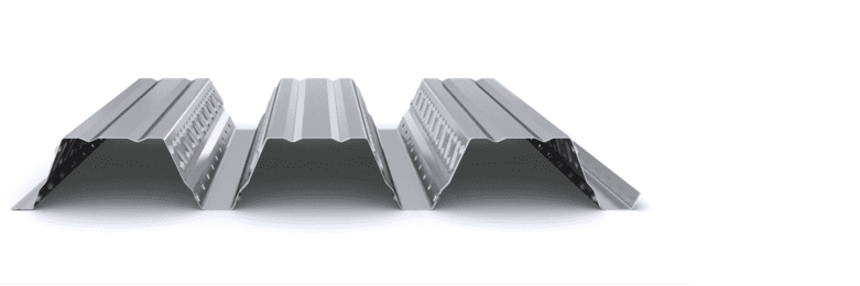
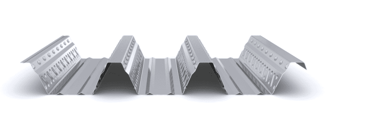
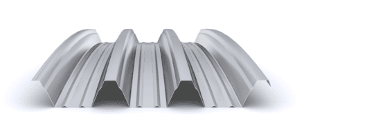
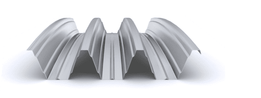
  • Profile: INCO 100.3 Composite Deck
  • Sheet thickness: 1.20 mm
  • Spans in the composite stage: 4 equal spans
  • Construction: unpropped composite floor
  • Required fire resistance: REI 90
  • Steel supports: 100 mm wide

Materials

  • Base steel: S320GD (resistance tables available for S280GD steel)
  • Structural concrete: HA-25

Loads

  • Additional permanent loads: 2.0 kN/m²
  • Imposed load: 3.0 kN/m²
  • Self-weight of the floor: taken into account internally by the calculation software

Verification criteria

  • Formwork stage: L/180 and an absolute limit of 20 mm, including the ponding effect.
  • Composite stage: L/700 + 5 mm (spans > 3.50 m).
  • Verification in accordance with Eurocodes 3 and 4, with fire resistance verified in accordance with EN 1994-1-2.

Structural solution adopted after verification

Applying the above criteria and verifying the formwork stage, composite stage and REI 90 fire resistance, the following reference configuration is obtained:

  • Total slab depth (H): 170 mm
  • Concrete topping depth (h): 70 mm
  • Top reinforcement mesh (crack control and negative reinforcement): 15×15×8
  • Bottom fire reinforcement: Ø10 mm in all ribs, positioned 65 mm from the bottom edge

The above configuration forms the common basis for both alternatives analysed. The maximum span achievable without propping depends on the structural arrangement adopted for the sheet during the formwork stage.

Variable analysed: sheet layout during the formwork stage

Two configurations are studied with identical loads, profile, slab depth and fire resistance. The variable analysed is the structural arrangement of the sheet during concrete pouring.

Option A — 1+1+1+1 layout (simply supported sheet)

Each span is constructed using an independent sheet, acting as a simply supported element during the formwork stage.

Maximum span without propping: 4.10 m

In this configuration:

  • The maximum positive moment occurs at mid-span.
  • Deflection during construction governs the design.
  • There is greater sensitivity to the ponding effect.

Option B — 2+2 layout (sheet continuous over two spans)

Each sheet covers two consecutive spans, creating structural continuity during the formwork stage.

Maximum span without propping: 4.60 m

The redistribution of forces reduces the positive moment at mid-span and generates a negative moment over the intermediate support, reducing the maximum deflection. This redistribution improves the behaviour of the sheet during the formwork stage and allows greater spans to be achieved without propping.

Structural interpretation

The increase from 4.10 m to 4.60 m, equivalent to approximately 12%, is not due to an increase in material or a greater amount of reinforcement, but exclusively to the change in the structural arrangement during the formwork stage.

With a simply supported arrangement:

  • Maximum positive moment at mid-span.
  • Higher deflection.
  • Greater sensitivity to ponding.

With a continuous arrangement:

  • Positive moment is reduced.
  • Negative moment develops over the support.
  • Maximum deflection is reduced.
  • Behaviour during the formwork stage is improved without the need for temporary props.

In both cases, the composite stage works as a continuous four-span slab. The difference occurs only during the construction stage.

Conclusion

For long spans without propping using the INCO 100.3 Composite Deck, sheet continuity during the formwork stage is decisive.

  • Simply supported layout (1+1+1+1): maximum span of approximately 4.10 m.
  • Continuous layout (2+2): maximum span of approximately 4.60 m.

This case confirms that, in unpropped composite floors, sheet continuity during the formwork stage is a decisive structural variable, with a direct impact on the achievable span and construction conditions. This type of comparative analysis is a structural optimisation tool during the design stage, allowing the design to be adapted to actual construction conditions and avoiding unnecessary over-dimensioning.

Composite floor calculation report

The above example is for guidance only and is based on specific assumptions regarding loads, span, fire resistance and structural arrangement.

The final design of an unpropped composite floor must be formalised through a specific calculation report, in which the following must be verified and documented:

  • Ultimate limit states (bending and shear).
  • Serviceability limit states during the formwork and composite stages.
  • Fire resistance in accordance with EN 1994-1-2.
  • Construction conditions and adopted structural arrangement.

The Incoperfil Technical Department issues supporting calculation reports adapted to the actual conditions of each project, in accordance with Eurocodes 3 and 4. A report can be requested through the technical form available on the website, providing spans, loads and fire-resistance requirements.

Request the composite floor calculation report through the following link: Composite Floor Calculation Report

Related articles

Incoperfil Technical Manual

For the complete definition of the system, design criteria, calculation bases, resistance tables, construction details and installation procedures, please refer to the Incoperfil Technical Manual for Composite Floors, available upon registration in the Documentation section of the website.


Last updated: September 2026

© Incoperfil. All rights reserved.
The technical content of this article forms part of the Technical Manual for Composite Floors and the documentation registered by Incoperfil with ColorIURIS (Record No. 1-INCOPERFIL-12.2025).

Home / 23. Long Spans Without Propping with INCO 100.3

Guía técnica

24942

23. Long Spans Without Propping with INCO 100.3

Technical design example using INCO 100.3 Composite Deck and REI 90 for long spans without propping. The analysis compares two sheet layouts during the formwork stage and shows how continuity makes it possible to increase the maximum achievable span from 4.10 m to 4.60 m.

Calculation example of an unpropped composite floor

The purpose of this example is to analyse the influence of the structural arrangement of the sheet during the formwork stage. Two layouts — 1+1+1+1 and 2+2 — are compared, keeping the 1.20 mm INCO 100.3 Composite Deck, loads, floor depth and REI 90 requirement constant. This makes it possible to directly assess the effect of sheet continuity on the achievable span without propping.

Starting assumptions

The following initial conditions are considered:

Geometry and arrangement

  • Profile: INCO 100.3 Composite Deck
  • Sheet thickness: 1.20 mm
  • Spans in the composite stage: 4 equal spans
  • Construction: unpropped composite floor
  • Required fire resistance: REI 90
  • Steel supports: 100 mm wide

Materials

  • Base steel: S320GD (resistance tables available for S280GD steel)
  • Structural concrete: HA-25

Loads

  • Additional permanent loads: 2.0 kN/m²
  • Imposed load: 3.0 kN/m²
  • Self-weight of the floor: taken into account internally by the calculation software

Verification criteria

  • Formwork stage: L/180 and an absolute limit of 20 mm, including the ponding effect.
  • Composite stage: L/700 + 5 mm (spans > 3.50 m).
  • Verification in accordance with Eurocodes 3 and 4, with fire resistance verified in accordance with EN 1994-1-2.

Structural solution adopted after verification

Applying the above criteria and verifying the formwork stage, composite stage and REI 90 fire resistance, the following reference configuration is obtained:

  • Total slab depth (H): 170 mm
  • Concrete topping depth (h): 70 mm
  • Top reinforcement mesh (crack control and negative reinforcement): 15×15×8
  • Bottom fire reinforcement: Ø10 mm in all ribs, positioned 65 mm from the bottom edge

The above configuration forms the common basis for both alternatives analysed. The maximum span achievable without propping depends on the structural arrangement adopted for the sheet during the formwork stage.

Variable analysed: sheet layout during the formwork stage

Two configurations are studied with identical loads, profile, slab depth and fire resistance. The variable analysed is the structural arrangement of the sheet during concrete pouring.

Option A — 1+1+1+1 layout (simply supported sheet)

Each span is constructed using an independent sheet, acting as a simply supported element during the formwork stage.

Maximum span without propping: 4.10 m

In this configuration:

  • The maximum positive moment occurs at mid-span.
  • Deflection during construction governs the design.
  • There is greater sensitivity to the ponding effect.

Option B — 2+2 layout (sheet continuous over two spans)

Each sheet covers two consecutive spans, creating structural continuity during the formwork stage.

Maximum span without propping: 4.60 m

The redistribution of forces reduces the positive moment at mid-span and generates a negative moment over the intermediate support, reducing the maximum deflection. This redistribution improves the behaviour of the sheet during the formwork stage and allows greater spans to be achieved without propping.

Structural interpretation

The increase from 4.10 m to 4.60 m, equivalent to approximately 12%, is not due to an increase in material or a greater amount of reinforcement, but exclusively to the change in the structural arrangement during the formwork stage.

With a simply supported arrangement:

  • Maximum positive moment at mid-span.
  • Higher deflection.
  • Greater sensitivity to ponding.

With a continuous arrangement:

  • Positive moment is reduced.
  • Negative moment develops over the support.
  • Maximum deflection is reduced.
  • Behaviour during the formwork stage is improved without the need for temporary props.

In both cases, the composite stage works as a continuous four-span slab. The difference occurs only during the construction stage.

Conclusion

For long spans without propping using the INCO 100.3 Composite Deck, sheet continuity during the formwork stage is decisive.

  • Simply supported layout (1+1+1+1): maximum span of approximately 4.10 m.
  • Continuous layout (2+2): maximum span of approximately 4.60 m.

This case confirms that, in unpropped composite floors, sheet continuity during the formwork stage is a decisive structural variable, with a direct impact on the achievable span and construction conditions. This type of comparative analysis is a structural optimisation tool during the design stage, allowing the design to be adapted to actual construction conditions and avoiding unnecessary over-dimensioning.

Composite floor calculation report

The above example is for guidance only and is based on specific assumptions regarding loads, span, fire resistance and structural arrangement.

The final design of an unpropped composite floor must be formalised through a specific calculation report, in which the following must be verified and documented:

  • Ultimate limit states (bending and shear).
  • Serviceability limit states during the formwork and composite stages.
  • Fire resistance in accordance with EN 1994-1-2.
  • Construction conditions and adopted structural arrangement.

The Incoperfil Technical Department issues supporting calculation reports adapted to the actual conditions of each project, in accordance with Eurocodes 3 and 4. A report can be requested through the technical form available on the website, providing spans, loads and fire-resistance requirements.

Request the composite floor calculation report through the following link: Composite Floor Calculation Report

Related articles

Incoperfil Technical Manual

For the complete definition of the system, design criteria, calculation bases, resistance tables, construction details and installation procedures, please refer to the Incoperfil Technical Manual for Composite Floors, available upon registration in the Documentation section of the website.


Last updated: September 2026

© Incoperfil. All rights reserved.
The technical content of this article forms part of the Technical Manual for Composite Floors and the documentation registered by Incoperfil with ColorIURIS (Record No. 1-INCOPERFIL-12.2025).