
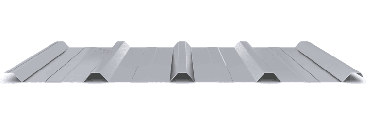
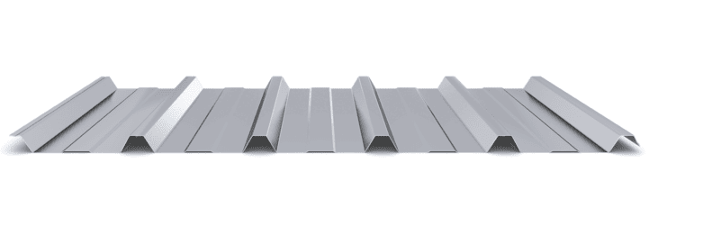
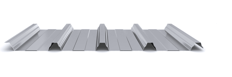
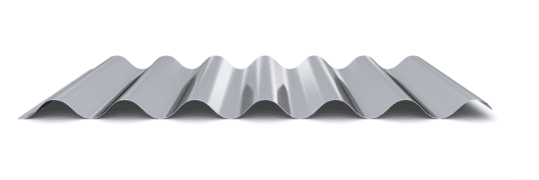
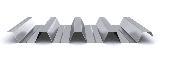

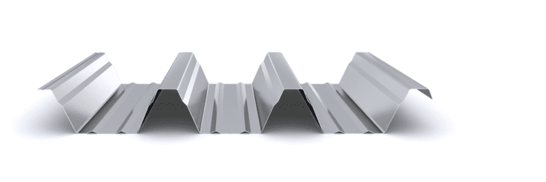



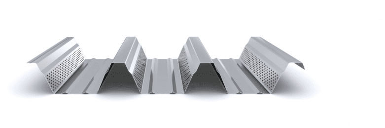
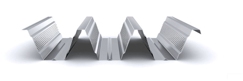
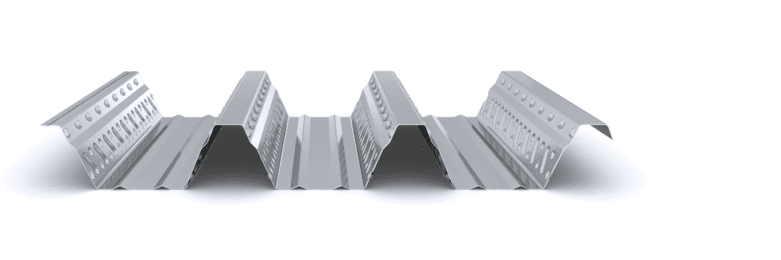
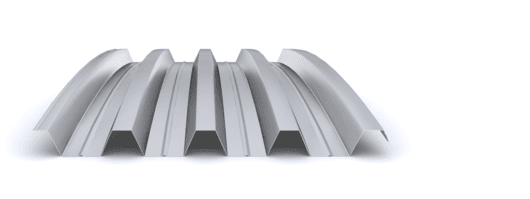
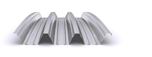

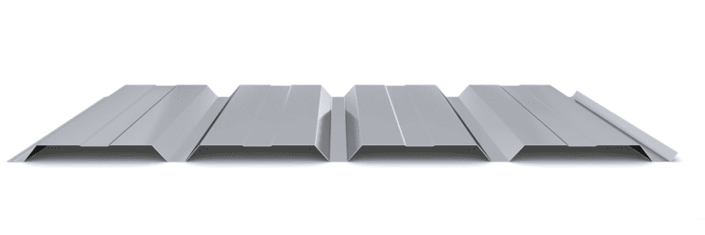
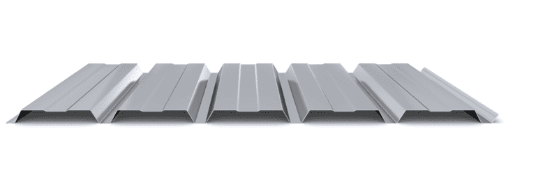
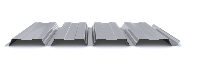
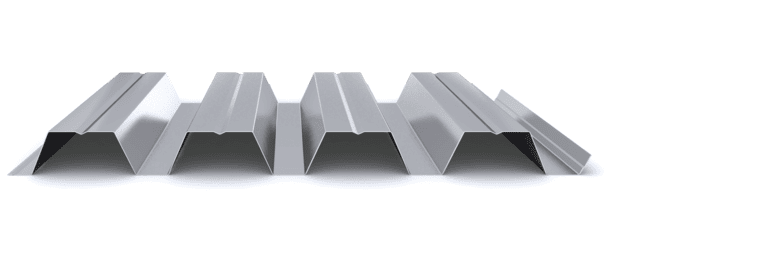


The purpose of this example is to analyse how support spacing affects the design and structural efficiency of a composite floor deck. Two solutions are compared for the same overall floor length by changing the support arrangement and assessing the resulting effects on the load-bearing section, the materials required and the construction conditions.
The comparison illustrates a common design consideration: where the spacing between primary beams is large, it may be beneficial to bring the supports closer together, add secondary beams or change the floor span direction so that the composite deck sheet spans within a more efficient range.
Initial assumptions
The following assumptions are used:
Geometry and structural arrangement
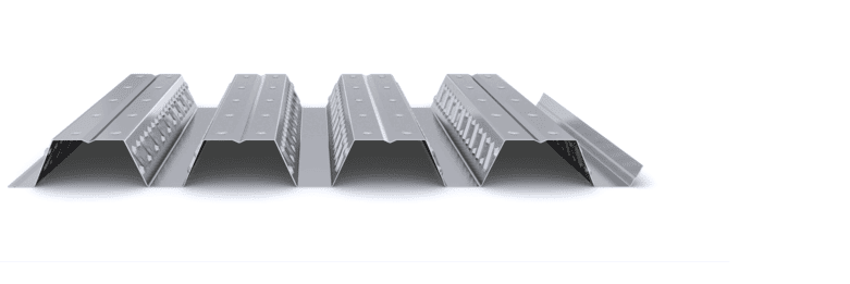
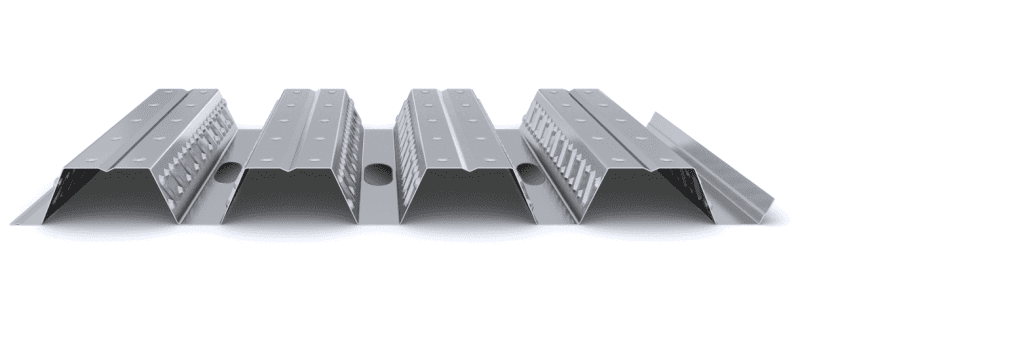
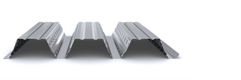
- Profile: INCO 70.4 Composite Deck
- Design configuration C1:
- Composite stage: 4 equal spans of 2.50 m (2.5 + 2.5 + 2.5 + 2.5 m)
- Formwork stage: 2 sheets, each spanning 2 × 2.50 m
- Design configuration C2:
- Composite stage: 2 equal spans of 5.00 m (5 + 5 m)
- Formwork stage: 1 sheet spanning 2 × 5.00 m
- Total length analysed: 10.00 m in both configurations
- Construction: composite floor deck, with a check to determine whether propping is needed during the formwork stage
- Required fire resistance: REI 30
- Steel supports: 100 mm wide
Materials
- Base steel: S280GD
- Structural concrete: HA-25
Actions
- Additional permanent load considered: 2.0 kN/m²
- Imposed load: 5.0 kN/m²
- Floor deck self-weight: included internally in the calculation software
Verification criteria
- Formwork stage: L/180 and an absolute limit of 20 mm, including the ponding effect
- Composite stage:
- L/350 for spans less than or equal to 3.50 m
- L/700 + 5 mm for spans greater than 3.50 m
- Verification in accordance with Eurocodes 3 and 4; fire resistance in accordance with UNE-EN 1994-1-2
Comparative results
Applying the assumptions above and checking the formwork stage, composite stage and REI 30 fire resistance gives the following results:
Configuration C1 — Four spans of 2.50 m
Configuration C1 uses closer support spacing, with four equal spans of 2.50 m.
Main results:
- Sheet thickness: 0.75 mm
- Total floor depth (H): 120 mm
- Concrete topping thickness (h): 50 mm
- Top reinforcement mesh: 150×150×6
- Floor deck self-weight: 1.83 kN/m²
- Rows of props during the formwork stage: not required
This configuration allows the floor to be built using the thinnest sheet considered and the minimum slab depth used in this example. The 2.50 m support spacing places the system in a favourable range for the formwork stage, reducing deflection during concrete pouring and avoiding the need for intermediate props.
From a construction perspective, this is a simple, lightweight and efficient solution for the composite floor deck system itself.
Configuration C2 — Two spans of 5.00 m
Configuration C2 uses wider support spacing, with two equal spans of 5.00 m.
Main results:
- Sheet thickness: 1.20 mm
- Total floor depth (H): 210 mm
- Concrete topping thickness (h): 140 mm
- Top reinforcement mesh: 150×150×12
- Floor deck self-weight: 3.96 kN/m²
- Rows of props during the formwork stage: 1 row per span
This configuration can also be structurally verified, but it requires a considerably more robust solution. The increased span requires a thicker sheet, a greater total floor depth and more top reinforcement. It also requires propping during construction.
The 5.00 m span is therefore less favourable in terms of deflection, self-weight and construction requirements. It is not an unfeasible configuration, but it falls outside the system’s most efficient range when intermediate supports can be provided or the floor span direction can be changed.
Example outcome
Reducing the support spacing from 5.00 m to 2.50 m reduces the total floor depth by 90 mm and self-weight by approximately 54%, while also eliminating the need for propping.
| Parameter | C1 | C2 |
|---|---|---|
| Spans | 4 × 2.50 m | 2 × 5.00 m |
| Sheet thickness | 0.75 mm | 1.20 mm |
| Total floor depth | 120 mm | 210 mm |
| Top reinforcement mesh | 150×150×6 | 150×150×12 |
| Self-weight | 1.83 kN/m² | 3.96 kN/m² |
| Propping | No | 1 row at mid-span |
Structural interpretation
During the formwork stage, the composite deck sheet must support the weight of the fresh concrete, reinforcement and construction loads. As the span increases, bending and deflection demands rise, as does sensitivity to the ponding effect. For this reason, longer spans may require a thicker sheet or intermediate propping.
Once the concrete has hardened, the steel and concrete work together as a composite slab. At this stage, increasing the support spacing for the composite floor deck increases the internal forces, service deflections and need for adequate structural depth.
Cost and construction considerations
The comparison should not be interpreted solely in terms of the composite floor deck. The solution with supports every 2.50 m may require more secondary structure, while the 5.00 m solution reduces the number of supports but requires greater floor depth, self-weight and sheet thickness, and has more demanding construction requirements.
The best option should therefore be selected by considering the cost of the floor deck and secondary structure together, as well as the availability of sheet thicknesses and lengths, the need for propping and ease of installation.
Conclusion
This example shows that support spacing is a key factor in the design of a composite floor deck. Under the assumptions analysed, the solution using INCO 70.4 Composite Deck with 2.50 m spans significantly reduces floor depth, sheet thickness and self-weight, while avoiding the propping required for the 5.00 m configuration.
However, the optimisation must consider both the floor deck and the secondary structure, since reducing the spacing between beams does not necessarily result in a lower overall cost.
Composite floor deck calculation report
The example above is indicative and is based on specific assumptions regarding load, span, fire resistance, profile and structural arrangement.
The final design of a composite floor deck must be documented in a specific calculation report, verifying:
- Ultimate limit states (bending and shear)
- Serviceability limit states during the formwork and composite stages
- Fire resistance in accordance with UNE-EN 1994-1-2
- Construction conditions and the adopted structural arrangement
- Whether propping is required during concrete pouring
Incoperfil’s Technical Department prepares supporting calculation reports tailored to the actual conditions of each project, in accordance with Eurocodes 3 and 4. A report can be requested using the technical form available on the website. Please provide the spans, loads, structural arrangement and fire-resistance requirements.
Request a composite floor deck calculation report using the following link:
Composite floor deck calculation report
Related articles
- Support spacing for composite floor decks
- Composite deck profile thickness
- Composite floor deck without propping
- Long spans without propping with INCO 100.3
- Heavy loads without propping with INCO 70.4
- REI 180 composite floor deck: optimising floor depth
- Incoperfil Technical Manual
For full details of the system, design criteria, calculation bases, resistance tables, construction details and installation procedures, consult Incoperfil’s Technical Manual for Composite Floor Decks. It is available upon registration in the Documentation section of the website.
Last updated: October 2026
© Incoperfil. All rights reserved.
The technical content of this article forms part of the Technical Manual for Composite Floor Decks and the documentation registered by Incoperfil with ColorIURIS (Record No. 1-INCOPERFIL-12.2025).