
Request a
calculation form

14. Types of Reinforcement in Composite Flooring

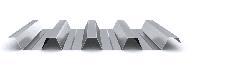
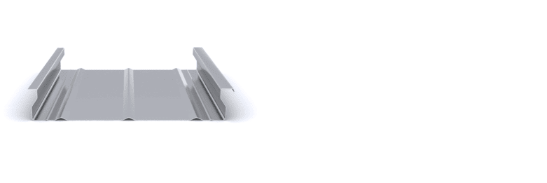
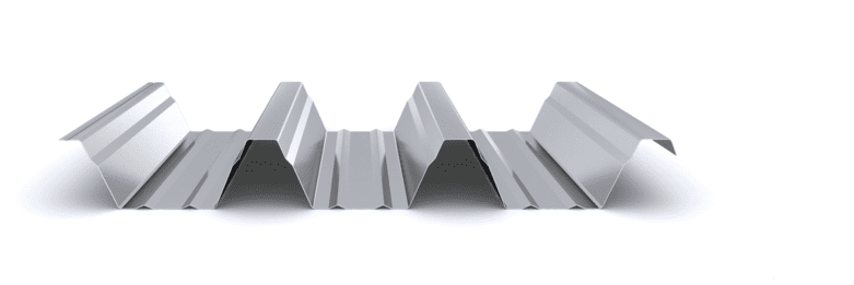
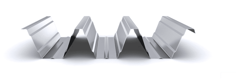
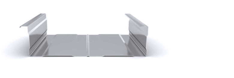
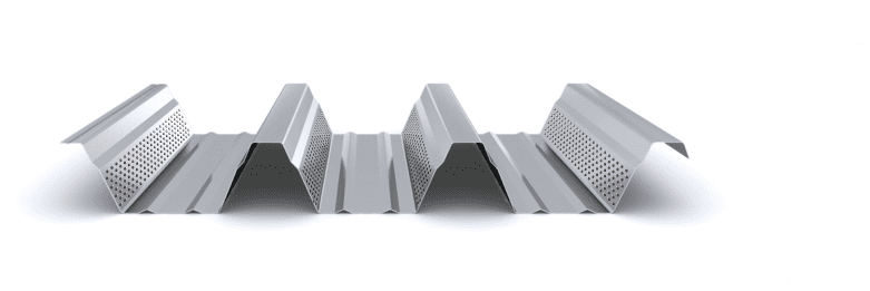
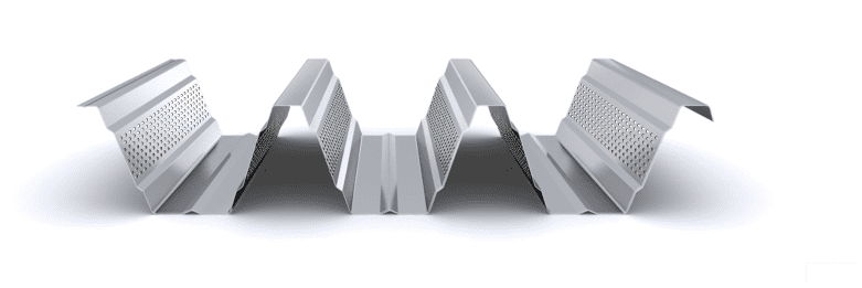
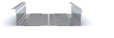
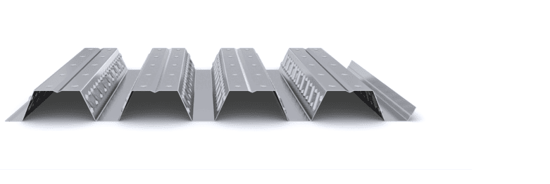
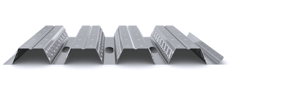
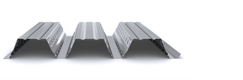
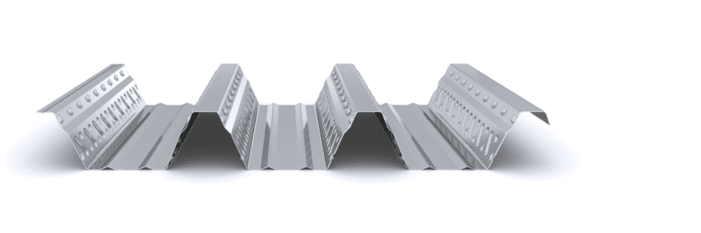
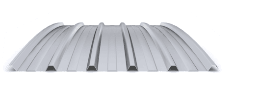
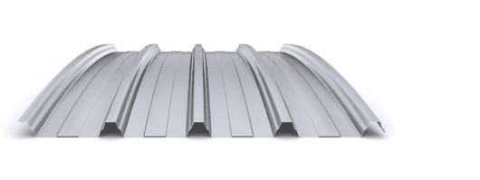
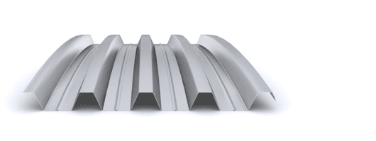
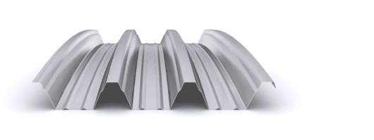
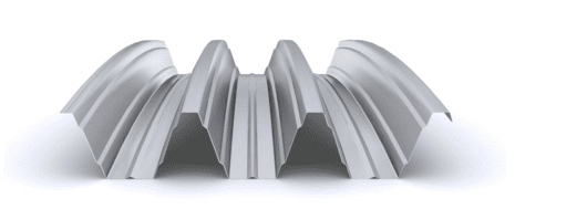
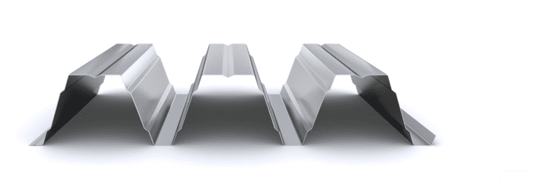
The correct design and arrangement of reinforcement — negative moment bars, positive or fire reinforcement, and top mesh — optimize the structural performance and durability of composite flooring. The INCO 70.4, INCO 100.3, and INCO 100.3 R profiles adapt to different reinforcement configurations and slab depths in accordance with applicable standards.

The different types of reinforcement used in composite flooring ensure the structural performance of the system during the service phase. These reinforcements control concrete cracking, ensure the load-bearing capacity of the composite slab, and allow compliance with fire resistance requirements defined in Eurocodes 3 and 4.

Types of Reinforcement in Composite Flooring

Depending on their position and structural function, the following can be distinguished:

  • Negative moment reinforcement.

  • Positive moment or fire reinforcement.

  • Anti-crack mesh (top reinforcement).

  • Local reinforcement bars.

Negative Moment Reinforcement

Negative moment reinforcement is placed in the upper part of the slab above intermediate supports in continuous floors to resist tensile forces generated in this area.

It is typically formed by bars placed above the rib axis and below the upper mesh. As a general guideline, its length extends approximately one-third of the span on each side of the support, although it must always be verified by structural calculation.

Typical diameters range between Ø6 and Ø16 mm. The compression layer thickness must ensure the minimum concrete cover required by the applicable standards, ensuring durability against corrosion.

Positive Moment or Fire Reinforcement

Positive moment reinforcement, also known as fire reinforcement, is placed in the lower part of the ribs inside the geometry of the composite profile. Its function is to resist tensile forces in the lower zone of the floor during the service phase.

In case of fire, this reinforcement maintains the load-bearing capacity of the system, allowing REI classifications to be achieved depending on slab depth and the reinforcement arrangement.

In Incoperfil profiles

  • In INCO 70.4 and INCO 100.3 R, the reinforcement is placed approximately 40 mm from the lower edge.

  • In INCO 100.3, it is located approximately 65 mm from the lower edge.

Typical diameters range between Ø6 and Ø16 mm, depending on design loads and fire-resistance requirements.

Anti-crack Mesh

The top mesh is primarily used to control cracking of the compression layer. In certain configurations, it may also contribute to resisting negative moments, reducing the need for additional reinforcement.

It is placed across the entire floor surface, typically with diameters between Ø6 and Ø12 mm and spacing between 150 and 200 mm, depending on project requirements.

It must be positioned within the compression layer, whose thickness must allow the minimum concrete cover required by standards and ensure adequate overall stiffness.

Local Reinforcement

In areas with load concentrations, openings, geometric changes, or structural discontinuities, additional longitudinal or transverse reinforcement may be placed to ensure proper redistribution of forces and limit localized cracking.

Reinforcement Design

The design of reinforcement in composite floors depends on span between supports, project loads, slab depth, number of spans, and fire-resistance requirements.

Verification must be carried out according to UNE-EN 1993-1-3, UNE-EN 1994-1-1, and UNE-EN 1994-1-2, checking ultimate limit states, serviceability limit states, and fire performance.

Conclusion

The proper combination of negative moment reinforcement, bottom positive or fire reinforcement, and top mesh ensures the structural performance and durability of composite flooring. Their arrangement must be defined through structural calculation, consistent with loads, system geometry, and project regulatory requirements.

Incoperfil Technical Manual

For a complete definition of the system, design criteria, calculation bases, resistance tables, construction details, and installation procedures, consult the Incoperfil Composite Slab Technical Manual, available upon registration in the Documentation section of the website.


Last update: February 2026

© Incoperfil. All rights reserved.
The technical content of this article forms part of the Composite Flooring Technical Manual and the documentation registered by Incoperfil with ColorURIS (Act No. 1-INCOPERFIL-12.2025).

Home / 14. Types of Reinforcement in Composite Flooring

Guía técnica

23451

14. Types of Reinforcement in Composite Flooring

The correct design and arrangement of reinforcement — negative moment bars, positive or fire reinforcement, and top mesh — optimize the structural performance and durability of composite flooring. The INCO 70.4, INCO 100.3, and INCO 100.3 R profiles adapt to different reinforcement configurations and slab depths in accordance with applicable standards.

The different types of reinforcement used in composite flooring ensure the structural performance of the system during the service phase. These reinforcements control concrete cracking, ensure the load-bearing capacity of the composite slab, and allow compliance with fire resistance requirements defined in Eurocodes 3 and 4.

Types of Reinforcement in Composite Flooring

Depending on their position and structural function, the following can be distinguished:

  • Negative moment reinforcement.

  • Positive moment or fire reinforcement.

  • Anti-crack mesh (top reinforcement).

  • Local reinforcement bars.

Negative Moment Reinforcement

Negative moment reinforcement is placed in the upper part of the slab above intermediate supports in continuous floors to resist tensile forces generated in this area.

It is typically formed by bars placed above the rib axis and below the upper mesh. As a general guideline, its length extends approximately one-third of the span on each side of the support, although it must always be verified by structural calculation.

Typical diameters range between Ø6 and Ø16 mm. The compression layer thickness must ensure the minimum concrete cover required by the applicable standards, ensuring durability against corrosion.

Positive Moment or Fire Reinforcement

Positive moment reinforcement, also known as fire reinforcement, is placed in the lower part of the ribs inside the geometry of the composite profile. Its function is to resist tensile forces in the lower zone of the floor during the service phase.

In case of fire, this reinforcement maintains the load-bearing capacity of the system, allowing REI classifications to be achieved depending on slab depth and the reinforcement arrangement.

In Incoperfil profiles

  • In INCO 70.4 and INCO 100.3 R, the reinforcement is placed approximately 40 mm from the lower edge.

  • In INCO 100.3, it is located approximately 65 mm from the lower edge.

Typical diameters range between Ø6 and Ø16 mm, depending on design loads and fire-resistance requirements.

Anti-crack Mesh

The top mesh is primarily used to control cracking of the compression layer. In certain configurations, it may also contribute to resisting negative moments, reducing the need for additional reinforcement.

It is placed across the entire floor surface, typically with diameters between Ø6 and Ø12 mm and spacing between 150 and 200 mm, depending on project requirements.

It must be positioned within the compression layer, whose thickness must allow the minimum concrete cover required by standards and ensure adequate overall stiffness.

Local Reinforcement

In areas with load concentrations, openings, geometric changes, or structural discontinuities, additional longitudinal or transverse reinforcement may be placed to ensure proper redistribution of forces and limit localized cracking.

Reinforcement Design

The design of reinforcement in composite floors depends on span between supports, project loads, slab depth, number of spans, and fire-resistance requirements.

Verification must be carried out according to UNE-EN 1993-1-3, UNE-EN 1994-1-1, and UNE-EN 1994-1-2, checking ultimate limit states, serviceability limit states, and fire performance.

Conclusion

The proper combination of negative moment reinforcement, bottom positive or fire reinforcement, and top mesh ensures the structural performance and durability of composite flooring. Their arrangement must be defined through structural calculation, consistent with loads, system geometry, and project regulatory requirements.

Incoperfil Technical Manual

For a complete definition of the system, design criteria, calculation bases, resistance tables, construction details, and installation procedures, consult the Incoperfil Composite Slab Technical Manual, available upon registration in the Documentation section of the website.


Last update: February 2026

© Incoperfil. All rights reserved.
The technical content of this article forms part of the Composite Flooring Technical Manual and the documentation registered by Incoperfil with ColorURIS (Act No. 1-INCOPERFIL-12.2025).