
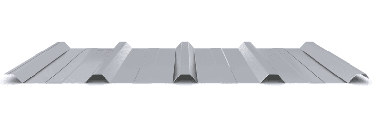
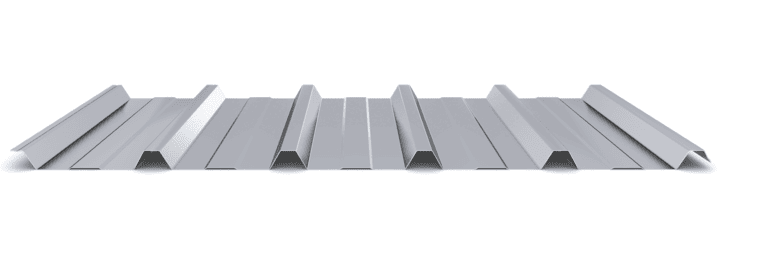
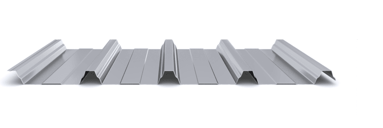
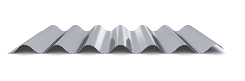



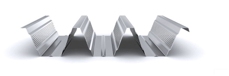
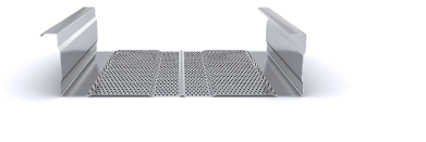
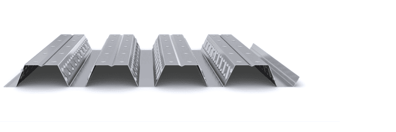
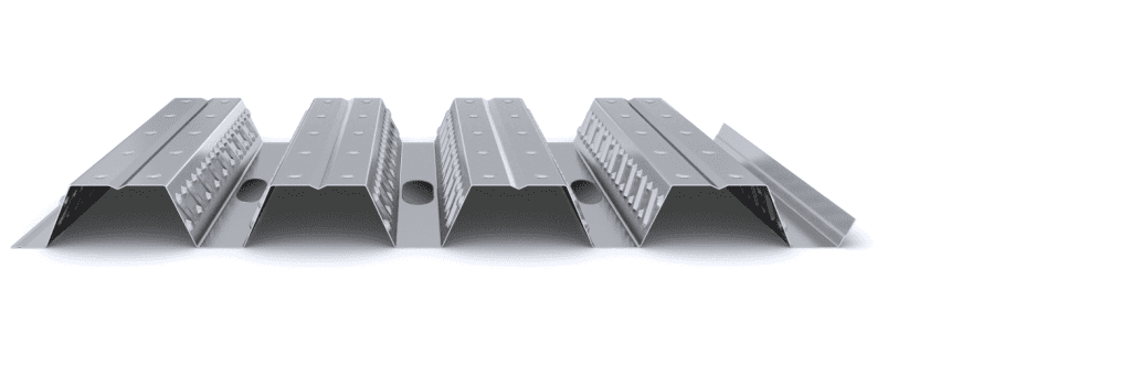
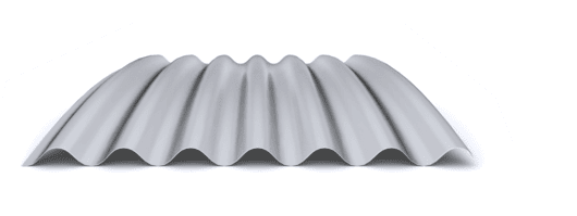
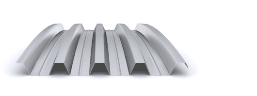
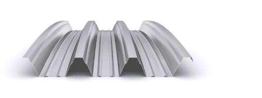
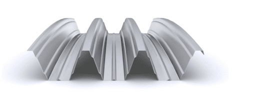
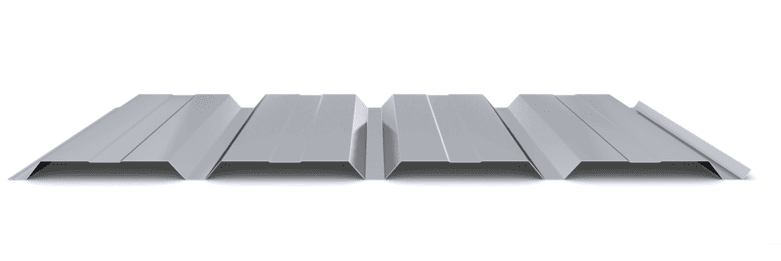
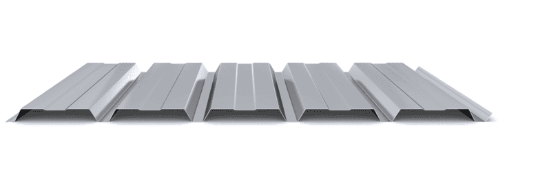
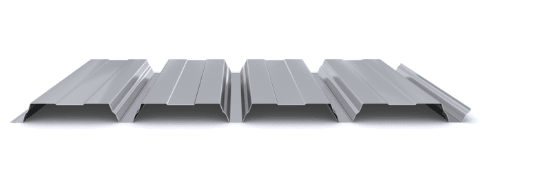
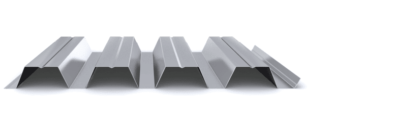


Selecting a composite floor deck profile is not simply a matter of choosing the one with the greatest span or load capacity in a table. The solution must be checked during the construction stage, the composite stage and under fire conditions, and each stage may be governed by different constraints. This article summarises that approach and links the selection criteria to the worked calculation examples in the guide.
Identifying the governing design variable for a composite floor deck
Three major structural constraints apply simultaneously to a composite floor deck:
- Clear span between supports.
- Load level (dead loads and imposed loads).
- Fire resistance requirement (REI).
Although all these variables must be checked, they do not necessarily have the same influence. A project may have different governing constraints for the construction stage, the composite stage and fire resistance. Identifying which checks govern each solution helps guide the profile selection and avoid unnecessary overdesign.
1. When span is the governing variable
In projects requiring large open spaces, such as open-plan offices, retail areas or multi-purpose buildings, the distance between supports may become the governing design variable. The aim is to achieve longer structural spans, even if temporary propping is needed during construction.
In these cases, the construction stage is especially important. Deflection criteria (L/180 and the absolute limit) may govern the design before the ultimate limit states do.
Choosing a profile with greater strength and stiffness during the construction stage may allow you to:
- Achieve longer spans without necessarily increasing the deck thickness.
- Reduce or eliminate lines of props.
- Improve construction productivity.
Examples covered in the guide:
2. When load is the governing variable
In industrial buildings, plant areas or car parks with high imposed loads, load may become the governing design variable.
In this scenario:
- The composite stage will usually govern.
- Checks for bending, shear and deflection during the composite stage are especially important.
- Depending on the structural system adopted, a greater overall depth or additional reinforcement may be required.
Optimisation involves selecting a profile whose geometry can carry higher forces with the smallest possible increase in overall depth and additional reinforcement.
Example covered in the guide:
3. When fire resistance is the governing variable
Where high fire-resistance ratings are required, such as REI 120 or REI 180, the thermal insulation criterion may govern the minimum floor depth. At the same time, the load-bearing capacity during a fire must be checked by determining the required arrangement and quantity of reinforcement, in accordance with UNE-EN 1994-1-2.
In these cases:
- Thermal insulation (criterion I) may govern the minimum floor depth.
- The position and quantity of the bottom reinforcement affect load-bearing capacity (criterion R).
- The profile geometry influences the behaviour of the assembly in a fire.
As a result, meeting the thermal insulation criterion may require a greater minimum floor depth than the mechanical checks alone would require.
Example covered in the guide:
Simplified selection guidance
As a general guide, the following conceptual framework can be used:
| Governing variable | Main consequence | Profile selection criteria |
|---|---|---|
| Span | Strength and deflection during the construction stage | Profile capacity and stiffness, deck layout and propping |
| Load | ULS and SLS during the composite stage | Load-bearing capacity, floor depth and required reinforcement |
| Fire (high REI rating) | Insulation (I) and load-bearing capacity (R) | Floor depth, profile geometry and bottom reinforcement |
This framework does not replace a full structural design, but it helps organise the initial decision-making stage.
Common design-stage errors
The following errors are frequently seen in professional practice:
- Selecting a profile based on previous projects or product availability.
- Focusing the checks exclusively on the composite stage.
- Failing to distinguish the behaviour during the construction stage.
- Failing to assess the effect of propping on the schedule and cost.
- Overlooking that the thermal insulation criterion under fire conditions may require a greater minimum floor depth than the structural checks do.
- Failing to distinguish the actual deck layout during the construction stage from the final structural system of the slab during the composite stage.
Rational design of a composite floor deck requires simultaneous consideration of:
- Ultimate limit states.
- Serviceability limit states.
- Fire resistance in accordance with UNE-EN 1994-1-2.
- Actual construction conditions.
Conclusion
Profile selection should begin by identifying the checks that govern the design at each project stage. The span between supports, the loads and the fire-resistance requirement may impose different constraints on floor depth, reinforcement and construction conditions.
Comparing solutions while considering the construction stage, the composite stage and fire resistance together makes it possible to select the most suitable profile, avoid overdesign, and account for the need for propping and the overall cost of the solution.
Composite floor deck calculation report
The final design of a composite floor deck must be documented in a project-specific calculation report, including documented checks of:
- Ultimate limit states during the construction and composite stages.
- Serviceability limit states during the construction and composite stages.
- Fire resistance in accordance with UNE-EN 1994-1-2.
- Construction conditions and the structural system adopted.
Incoperfil’s Technical Department issues supporting calculation reports tailored to the actual conditions of each project, in accordance with Eurocodes 3 and 4. You can request a report using the technical form available on the website, providing the spans, loads and fire-resistance requirements.
Request a composite floor deck calculation report using the following link:
Composite floor deck calculation report
Related articles
- How to design a composite floor deck.
- How to calculate a composite floor deck.
- Types and selection of composite floor deck profiles.
- Fire resistance of composite floor decks.
Incoperfil Technical Manual
For a complete description of the system, design criteria, design basis, resistance tables, construction details and installation procedures, consult Incoperfil’s Technical Manual for Composite Floor Decks, available upon registration in the Documentation section of the website.
Last updated: October 2026
© Incoperfil. All rights reserved.
The technical content of this article forms part of the Technical Manual for Composite Floor Decks and the documentation registered by Incoperfil with ColorIURIS (Record No. 1-INCOPERFIL-12.2025).